
Introduction to PCB Manual Soldering

This technical document is specially prepared for electronics enthusiasts who wish to learn soldering techniques. It provides a complete explanation of manual soldering methods for printed circuit boards, covering the selection of soldering tools, material preparation, detailed operating steps, advanced skills, and troubleshooting of common problems. Beginners can gradually carry out soldering projects by following the instructions in the document, while experienced soldering operators can also learn more professional treatment methods from it.
Manual soldering is a process that is used to connect electronic components to printed circuit boards (PCBs). The operator uses a soldering iron to provide the necessary heat and completes the connection by means of a fusible alloy known as solder. Automated soldering equipment is typically tasked with mass production work. In contrast, manual soldering plays an irreplaceable role in prototyping, equipment repair and the assembly of complex small-batch PCBs.
Several factors determine the success of soldering operations. The operator must deliver heat from the solder precisely to the target joint. The choice of soldering iron depends on the specific soldering task. Operators also need to understand the interaction between temperature, flux, and solder. There is a common core set of techniques for soldering through-hole components and surface-mount devices. Mastery of these techniques allows operators to produce printed circuit boards with long service life and stable performance, ensuring trouble-free operation.
What Is PCB Manual Soldering? Hand Soldering Explained
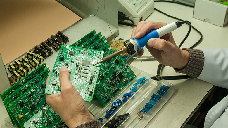
Manual soldering refers to the process by which an operator uses a soldering iron to heat and melt solder wire, then assembles components onto a circuit board (PCB). The molten solder wire connects its two ends to pads on the PCB. This connection ultimately forms a structure that serves a dual function: providing a path for electrical current and providing a mechanical connection to secure electronic components. Here, “manual soldering” specifically refers to PCB soldering, i.e., the process by which an operator manually assembles electronic components onto a circuit board. This process differs from assembly methods that use automated methods such as reflow ovens or wave soldering machines.
Soldering involves heat: The tip of a soldering iron needs to reach a specific temperature range. This temperature must be high enough to melt the solder, yet not excessively high—it is to prevent damage to the pads on the printed circuit board (PCB) and avoid harming precision electronic components. The complete process of soldering operations can be broken down into the following steps for detailed illustration:
- Apply heat to both component and PCB pad using the iron tip.
- Feed solder wire until it melts onto the PCB.
- Remove the heat and let the solder solidify.
Manual soldering features two prominent advantages. The operator can flexibly adjust their soldering techniques according to the actual conditions during the welding process. For defective or structurally complex solder joints, the operator can also carry out individual treatment and rework on them. PCB assemblies completed with exquisite soldering techniques offer superior structural quality. The solder joint connections of such assemblies are more firm and reliable. When conducting subsequent equipment maintenance, the operator can handle these assemblies with greater convenience.
Understanding the PCB: Printed Circuit Board Fundamentals
Printed Circuit Board (PCB) is the backbone of modern electronic devices. Its copper traces perform two fundamental functions: first, conducting electric current to supply power to all electronic components, and second, establishing electrical connections between various electronic components. The functionality of all electronic devices, from household thermostats to supercomputers, is built on this system.
- PCB traces: These are the copper paths that conduct electrons between pads and components.
- Pads and vias: Pads are specific points on the surface of a printed circuit board (PCB) where component leads establish electrical connections with the board. Vias are tiny holes that penetrate the laminated structure of a PCB, with their inner walls metallized. These tiny holes are responsible for connecting the copper traces between different layers of the PCB. Together, pads and vias form the fundamental structure for component assembly on a PCB.
- Through-hole vs. Surface Mount: Through-hole components have leads of sufficient length to pass through the pre-drilled holes on a printed circuit board (PCB). Surface mount technology (SMT) components, however, adopt a different assembly method. The design of the latter ensures their leads do not need to pass through the board; instead, they are directly mounted on the pads on the PCB surface. These are two distinct structural types for component assembly on printed circuit boards.
Operators who adopt a reliable printed circuit board (PCB) soldering process will ultimately achieve high-quality solder joints.Over the entire service life of electronic equipment, each solder joint must meet several key requirements at the same time:it must have sufficient mechanical strength to resist physical vibration and external forces,maintain good electrical conductivity to ensure unobstructed current transmission,and feature long-term stability to resist environmental corrosion and withstand long-term aging.
LHD TECH’S Essential Soldering Tools and Materials
Tools and materials form the foundation of all soldering operations. Operators need to be equipped with a full set of essential soldering tools. With proper tools in place, every soldering task can be carried out more smoothly, the operator’s safety is better ensured and the final construction quality is more likely to meet the desired standards.
Must-Have Soldering Tools Table
| Tool/Material | Purpose | Best Practice |
| Soldering Iron/Station | Main tool to heat and melt solder | Use adjustable temp for different solder types |
| Fine-tipped iron | Precise soldering of SMD/fine-pitch components | Choose for advanced soldering or SMT |
| Solder Wire (tin/lead-free) | Metal alloy that forms solder joints | Use flux-core solder for easier operation |
| Flux | Improves solder flow and joint quality | Apply additional flux when soldering tough spots |
| Cleaning sponge or brass wool | Cleans oxidation from iron tip | Clean frequently for best soldering output |
| Solder wick/desoldering pump | Removes excess solder | Critical for reworking soldering defects |
| Tweezers/pliers | Places and holds components during soldering tasks | Prefer ESD-safe tools for sensitive items |
| Magnifying lamp | Reveals tiny soldering defects or bridges | Indispensable for fine work and inspection |
| Fume extractor/fan | Ensures safe air when soldering with flux | Always use, especially in long soldering sessions |
| PCB holder (“helping hands”) | Secures the PCB while you work | Provides stability for proper soldering technique |
| Safety gear | Glasses, gloves for protection | Required for any soldering environment |
Welders must prepare all tools and materials before starting to weld. Correct selection of these tools and materials is the solid foundation for every welding operation. This preparation will greatly improve the success rate of the entire welding process.
Choosing the Right Soldering Iron and Solder
It is critical for soldering operators to select the appropriate soldering iron.The power of the soldering iron directly affects the soldering operation.Whether the soldering iron has a temperature control function also influences the soldering process.The choice of soldering iron tip likewise has an effect on soldering quality.Combined, these factors ultimately determine the quality of the soldering results.
- Soldering station: Offers precise temperature control and changeable tips for different soldering tasks.
- Fine-tipped soldering iron: A must for advanced soldering tasks (like SMD or complex PCB assemblies).
- Chisel/flat tips: Good for through-hole and larger connections.Fine-tipped points are best for small components.
- Soldering equipment: Don’t skimp—high-quality soldering stations maintain temperature better, lengthening the lifespan of the soldering tip.
Solder types:
- Tin-lead solder(e.g., 60/40 mesh) melts at lower temps and is more forgiving (not always RoHS compliant).
- Lead-free solder(with silver or copper) requires slightly higher heat and more flux, but is safer and required for commercial products.
- Silver soldering and brazing: High-strength, high-temp joining for mechanical or special PCB connections.
Flux when soldering: Always use flux—whether built into solder wire or separately applied—to fight oxidation during soldering and to guarantee a reliable electrical/mechanical joint.
Best Practices: Setup, Preparation and Safety
Setting up a soldering workstation is a fundamental skill in hand soldering. The operator needs to arrange tools and materials properly to prevent the soldering iron’s power cord from obstructing the operation. The operator also needs to ensure sufficient lighting in the work area. A magnifying lamp is a practical auxiliary tool, offering significant value for inspecting PCB assemblies and troubleshooting soldering defects.
Before you start soldering, ensure your PCB or components are free of dust and oxidation. Use isopropyl alcohol and a lint-free cloth to clean the pcb traces and pads—this step is non-negotiable for high-quality solder. Even experienced professionals know that oxidation during soldering can cause cold joints and weak conductivity.
Use Safety Equipment:
- Always wear safety glasses to protect from accidental splashes of molten solder.
- Keep your fume extractor running and work in a well-ventilated area—flux fumes are harmful over time.
- Use heat-resistant gloves when handling the soldering iron or when working with large or metallic PCBs that conduct heat away rapidly.
Through-Hole Soldering: The Classic Technique

Through-hole soldering remains one of the most accessible and reliable soldering techniques for both DIYers and professional electronics assembly. In this manual soldering technique, leads of electronic components pass through pre-drilled holes in the PCB before being soldered on the opposite side.
LHD TECH’S Step-by-Step Through-Hole Soldering Process
- Insert the componentsinto the designated holes. Secure connectors and large components with tape to prevent movement.
- Flip the PCBand angle the tip of the soldering iron so both lead and PCB pad are heated simultaneously.
- Apply solder wireto the opposite side of the pad (not directly on the iron). Allow solder to flow and form a smooth, volcano-shaped mound around the lead.
- When the solder melts and fills the joint, remove the solder wire, then the iron. Allow the joint to cool naturally.
- Trim excess leadsclose to the solder joint using flush cutters, holding the leads to avoid shock to the PCB.
- Inspect each jointfor proper shape and shine, using a magnifier to check for solder bridges or insufficient solder.
Common Through-Hole Soldering Defects
| Defect | Cause | Solution |
| Cold joint | Not enough heat or oxidation | Clean & reheat with flux |
| Solder bridge | Too much solder or shaky technique | Remove with solder wick or pump |
| Lifted pad | Excessive heat or prying movement | Use correct temp; don’t force leads |
| Dull/rough finish | Insufficient cleaning or old solder | Always clean tips, replace if necessary |
Through-hole soldering is the process that builds resilient, repairable and long-lasting PCBs—making it ideal for beginner soldering skills and learning by doing.
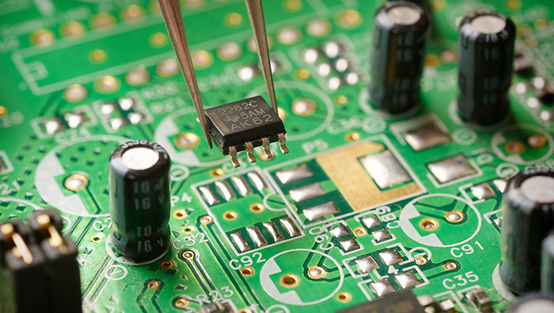
Surface Mount Technology (SMT) and Advanced Soldering
As electronics evolve, surface mount technology (SMT) and dense, compact PCB designs are standard in both consumer and industrial electronics. SMT relies on electronic components mounted directly onto the surface of the PCB rather than inserted through holes.
Mastering SMT Soldering Techniques
Tools and tips:
- Use a fine-tipped soldering iron with temperature control for small pads and pins.
- Apply liquid flux to SMT pads before positioning your components—this helps solder flow well during heating.
- Tack one pin of each SMD component, adjust placement, then solder the rest.
- For multi-pin ICs, practice drag soldering: apply flux generously, lay a bead of solder on the tip and gently pull across the pins. Excess solderor bridges can be removed with solder wick.
- For large or sensitive ICs (QFPs, BGAs)use a hot air rework station for heating and inspect under a microscope after soldering.
SMT Soldering: Best Practices
- Always pre-tin both the PCB pads and the component pins for better soldering results.
- Clean any excess flux residue after assembly.Especially important for high-frequency or sensitive electronics as residue can corrode traces or form leakage paths.
- For reflow soldering, use solder paste (a mixture of powdered solder and flux). Precise paste application is critical for proper joint formation.
LHD TECH’S Step-by-Step Process of Soldering: Soldering Techniques for All Levels

Whether through-hole, SMT or complex soldering, perfecting your process of soldering ensures long-term reliability. Let’s review essential techniques and soldering tips for every skill level:
General Soldering Process
- Clean and arrange tools and materials: Set up your station for convenience and safety.
- Apply flux to pads and leads: This reduces oxidation and enhances solder flow.
- Pre-tin the iron tip: Apply and melt a bit of solder before starting each joint to improve heat transfer and prevent tip oxidation.
- Position the iron tip: For best results, ensure both pad and lead are heated together.
- Feed the solder: Let the solder melt and flow onto the PCB by touching the heated joint (not the iron directly).
- Remove heat carefully: Once solder flows, remove the iron without moving the component. Allow the joint to cool undisturbed.
- Inspect the joint: Use a magnifier to check for proper shape, voids or soldering defects.
Mastering Soldering Skills: Soldering with Expert Techniques
Master PCB soldering by practicing, observing and correcting small errors as you go. Pro soldering skills are built on attention to detail, patience and understanding what different soldering defects look like.
Soldering Tips from the Experts
- Replace the iron tip if it becomes pitted, excessively oxidized or won’t hold solder. This extends both the lifespan of the soldering tip and the quality of your work.
- For a successful soldering experience, avoid touching solder directly to the iron tip except when tinning.
- Rest the PCB flat on the workbench for surface mount or SMT soldering—this prevents components from shifting before solder melts.
- For reflow soldering with hot air, use low airflow to prevent blowing components away.
- Practice on scrap PCBs—when the solder joint appears shiny and forms a neat cone, you’re getting it right.
Advanced Soldering Task: Silver Soldering and Brazing
For power electronics or mechanical stress, you may encounter silver soldering—requiring higher heat and often used for connector shells, shields or wire-to-terminal joints. Always use a temperature-appropriate iron and consult datasheets for maximum allowed temperature on your PCB or components.
Identifying and Preventing Soldering Defects
Every comprehensive guide must teach you to spot and fix the most common faults—soldering defects can undermine even the most beautiful PCB.
| Defect | What It Looks Like | Prevention/Troubleshooting |
| Cold joints | Dull, cracked, or lumpy surface | Clean/flux, raise temp, reflow joint |
| Solder bridges | Solder shorts between adjacent pads | Use solder wick, adjust solder amount/technique |
| Lifted pads | Copper pad peeling off PCB | Lower temp, avoid excessive rework or force |
| Insufficient solder | Joint lacks proper coverage | Use more solder; ensure good flux and heat |
| Overheated pads | Discoloring, pad warps or lifts | Use temp control, preheat, and quick technique |
| Void in solder joint | Hole or bubble in solder | More flux, clean and retry |
Soldering Project Guide: Tips & Troubleshooting
Real-World Troubleshooting Example
Scenario: You solder a microcontroller, but it doesn’t program or communicate.
Solution:
- Inspect all related pads for cold joints and correct pin orientation.
- Test PCB traces with a continuity checker.
- Reflow selected pins with flux and check under a magnifier for hidden bridges.
Soldering Task Flow for Best Results
For every soldering project, proper sequence—especially with complex soldering involving both SMD and through-hole—makes a difference. Follow these best practices for a successful soldering experience:
- Start with smallest SMD components first to keep the board flat and stable.
- Move to vertical SMD or slightly larger chips.
- Continue with through-hole components, such as resistors and diodes, which keep the PCB close to the work surface.
- Finish with the bulkiest or tallest through-hole parts (like connectors or power supplies).
- Finish all solder joints with a thorough inspection under magnification to catch any soldering defects before they become failures in the field.
Automated vs. Manual Soldering Methods
Modern electronics production relies on automated soldering methods—wave soldering, selective soldering and reflow soldering—to handle large volumes and intricate designs quickly. However, automated soldering can’t always address the quirks and challenges that arise in specialized, high-value or prototype work.
Pros and Cons Table
| Method | Pros | Cons |
| Automated Soldering | Speed, uniformity, ideal for mass PCB assemblies | Expensive setup, inflexible, can miss defects |
| Manual Soldering | Flexible, ideal for repairs/complex projects, allows inspection | Slower, requires skilled operator |
Best soldering techniques blend both worlds: use automated soldering for basic PCB assemblies, and rely on manual soldering for rework, fine-pitch parts and anything the machines can’t handle.
When to Use Manual Soldering over Automated
- Prototypes: Constant design change demands human adaptability.
- Repair and rework: Fixing solder bridges, cold joints or upgrading components on finished PCBs.
- Custom/low-volume boards: Automation costs outweigh delivery/assembly speed.
Maintenance: Improve the Lifespan of the Soldering Tip
Your soldering iron tip is your most important interface with the PCB and solder. To maximize the lifespan of the soldering tip and ensure the best soldering every time, follow these essential soldering tips:
- Always keep the tip tinned.A thin layer of melted solder shields the tip from oxygen and minimizes oxidation during soldering.
- Clean the tip after every joint.Use a damp sponge or brass wool—avoid sandpaper (which destroys plating).
- Replace tips when pitting or erosion is visible.Solder won’t stick, and heat transfer plummets with damaged tips.
- After use, flood the tip with solder and then turn off your station.This preserves the plating and buys you hundreds more soldering tasks from the same tip.
Poor tip care leads to unreliable, frustrating soldering experiences and increases the risk of damaging PCBs during assembly or repair.
Frequently Asked Questions About PCB Manual Soldering Guide
Q: What type of solder is best for general electronics and PCB soldering?
A: Use rosin-core tin-lead solder (60/40 or 63/37) for the easiest manual soldering, unless lead-free is required. For modern commercial PCB assemblies, lead-free solders with a silver or copper component are preferred.
Q: Should I always use flux when soldering?
A: Yes, especially for advanced soldering and when working with lead-free or oxidized pads. Flux ensures proper solder flow and joint strength. High-quality solder comes with flux-core, but extra flux is always recommended for complex soldering projects.
Q: How can I avoid solder bridges during surface mount soldering?
A: Use a fine-tipped iron, less solder and lots of flux. If a bridge happens, touch with a clean solder wick or use the tip of the soldering iron to “sweep” away the excess.
Q: What’s the quickest way to remove and replace a through-hole component?
A: Use a desoldering pump or wick to clear the holes, add a bit of fresh solder to improve thermal contact and gently pull the component out as the solder melts.
Q: Should I invest in an advanced soldering station for hobbyist work?
A: Yes, if you plan on soldering regularly or working with SMD. The ability to control temperature extends tip life and ensures proper soldering techniques.
Q: How do I troubleshoot a PCB that’s still malfunctioning after inspection?
A: Check all connections for continuity, touch up suspect solder joints, and verify there are no hidden soldering defects (like cold joints or micro-bridges under ICs).
Conclusion: Start Soldering and Master PCB Assembly
This comprehensive guide is your blueprint for tackling any PCB manual soldering task, no matter how complex or advanced. By following the ultimate guide, using the right tools and materials, and honing your soldering skills with each project, you’ll experience the satisfaction and success of mastering PCB soldering.
Remember, hand soldering is more than a mechanical operation; it blends art and science and every joint is a badge of your expertise. Whether working on repairs, prototypes, or high-density PCB assemblies, the best soldering results come from a commitment to learning, practicing and using proper soldering techniques.
Don’t just start soldering—start soldering with expert care. Use this guide, consult the resources, and join the worldwide community of electronics innovators who understand that soldering is the process that makes all electronic design possible.