

Introduction
As LHD TECH, we are well aware of the core value of through-hole PCB assembly in modern electronic manufacturing – its outstanding reliability, ease of operation and structural strength make it the preferred solution for many high-demand application fields. As the name suggests, the core of this process lies in precisely inserting the leads of electronic components through the pre-drilled holes on the PCB and soldering them on the other side of the circuit board, thereby achieving both excellent mechanical fixation and stable electrical interconnection simultaneously.
This complete guide to through-hole PCB assembly walks beginners and seasoned hobbyists alike through every step in the process. You’ll learn not only how components are inserted and soldered but also industry insights on when this technique shines compared to the latest advancements, such as surface mount technology (SMT). If you’ve ever wondered what makes through-hole assembly offers so enduring in applications where mechanical strength and flexibility are key, this guide will give you the answers—plus plenty of practical tips for your next PCB project.
Understanding Through-Hole PCB Assembly
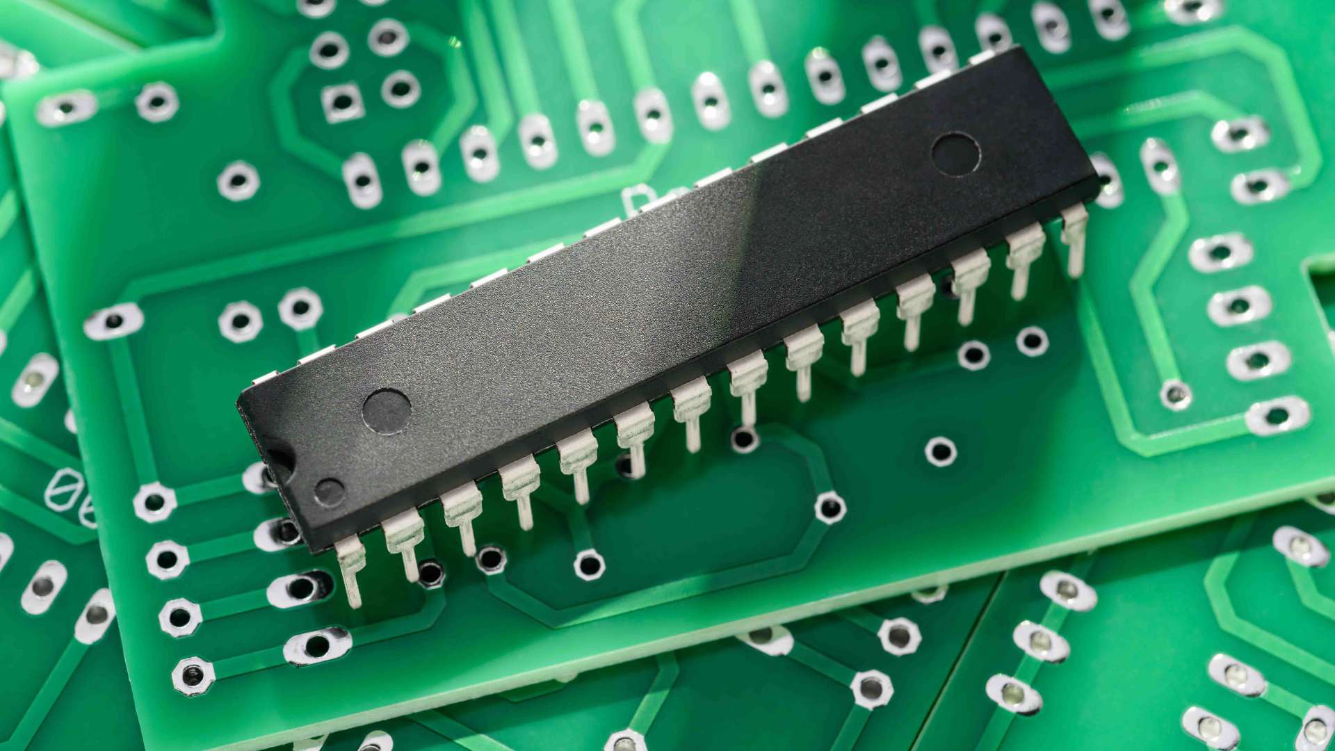
Through-hole assembly (THT PCB) is an assembly method that dates back to the earliest days of the PCB industry. Unlike SMT components, which are mounted directly onto PCB pads on the surface of the board, through-hole components are inserted into pre-drilled holes in the board (often called pads on the opposite side or vias).
The Basic Process Involves:
- Drilling holes:Precise holes are drilled into the PCB according to the PCB design.
- Inserting components:Leads of the components are inserted into these holes from one side.
- Soldering the leads:To ensure that the component pins precisely penetrate the board surface and extend to the welding side, the board is formed into a reliable electrical connection and mechanical fixation through a precisely controlled welding process.
- Inspection:Remember to conduct a strict quality check on each solder joint to ensure it is full and reliable, and eliminate any potential defects such as cold welding and bridging to prevent problems before they occur.
As LHD TECH, we are well aware of the irreplaceability of through-hole technology in specific application scenarios – especially for electronic components that need to withstand high mechanical stress, strong vibration environments or require frequent insertion and maintenance. The structural strength and maintenance convenience provided by this process have formed an unattainable core advantage in surface mount technology.
Why Choose Through-Hole Assembly?

Through-hole PCB assembly offers distinct advantages:
- Mechanical Strength: We are well aware that mechanical strength is a key indicator for measuring the reliability of electronic assembly. After the technical assessment, the mechanical structure formed by running the component pins through the PCB and completing the soldering on the opposite side can provide excellent resistance to mechanical stress. Therefore, in current application fields such as automotive electronics, military industry and industrial control, where mechanical strength and vibration resistance performance are extremely strict, this process has always been the preferred solution for design and selection.
- Ease of Prototyping and Repair: In prototypes or low-volume runs, engineers and makers can insert components, test, and swap parts easily—something not always possible with tiny SMT components. Through-hole assembly also allows for easier manual PCB assembly and repair on the fly.
- Greater Tolerance for Assembly Mistakes: If you’re new to electronics or working on educational PCB projects, through-hole is more forgiving. Components onto a PCB are easier to handle, leads are visible for checking orientation, and soldering the components is straightforward.
- Better for Power and High-Stress Applications: In our technical research, we are well aware of the key value of THT PCBS in the technical requirements of high-voltage and high-current scenarios, such as power modules, industrial control systems, and relay logic circuits. This assembly process, with its excellent heat dissipation performance and highly reliable mechanical connection, ensures the long-term stable operation of the system.
Through-Hole PCB Assembly Process: Step-by-Step Complete Guide
Mastering the through-hole PCB assembly process involves understanding every step in through-hole PCB assembly. Here, we break down the steps so both beginners and those with experience in the PCB industry can follow and succeed:
| Step | Description | Best Practices/Tips |
| 1. PCB Design | Use PCB design software to create a schematic, position electronic components, and specify drill holes, pad sizes and mounting. | Double-check component footprints and keep traces short for power paths. |
| 2. PCB Fabrication | Manufacturer fabricates the board, drills holes, applies solder masks, and adds silkscreen. | Inspect for clean holes drilled, well-defined pads, and correct layer registration. |
| 3. Inserting Components | Insert component leads into the holes from the top side. | Sort and bend leads in advance; insert in order of component height. |
| 4. Soldering the Components | Using a soldering iron, apply solder to the leads protruding from the opposite side to secure them to the pads. | Pre-tin the iron, use fresh solder, and heat both lead and pad for good solder flow. |
| 5. Inspection & Cleaning | Inspect for defects like cold joints or solder bridges; clean flux residues. | Use magnification and a multimeter for continuity; remove flux with alcohol. |
| 6. Final Testing | Power up and test the PCB for functionality. | Use a checklist to ensure no error in assembly. |
Key Processes in Through-Hole PCB Assembly
Drilling Holes
- In PCB assembly process involves the accuracy of drilling is of vital importance. Every position where components need to be inserted must have a precisely corresponding through hole to ensure the smooth progress of subsequent assembly.
- To ensure the stable insertion of components and reliable soldering, the hole diameter size, pin pitch, as well as the diameters of the top and bottom pads must all be strictly controlled. These design details directly determine the fit of the components and the final mechanical strength, and they are the key points of our process control.
Inserting Component Leads
- During the insertion process, our operators will ensure that each component is strictly aligned: for components like capacitors and diodes, the forward and reverse directions (polarity) must never be confused. As for ics and connectors, the placement Angle (orientation) should be carefully checked.
Soldering
- During the soldering process, we will use soldering irons to manually solder the component pins. The key point in operation is synchronous heating – the soldering iron tip touches both the pad and the pins simultaneously. Once the temperature reaches the set point, let the solder flow naturally and spread fully. This not only avoids defects such as cold welding, but also ensures that each weld point is full and reliable.
Inspection
- Check for issues like poor solder flow, incomplete filling of holes, bridges, or cold joints. All solder joints should appear shiny and conical, securely joining the lead and the pad.
How Through-Hole Technology Compares to Surface Mount Technology
Surface Mount Technology (SMT) is the dominant form of PCB assembly techniques in modern electronics. Still, through-hole PCB assembly persists due to several unique advantages:
| Feature | Through-Hole Technology | Surface Mount Technology |
| Mounting | Components inserted into holes | Components mounted to surface pads |
| Assembly Method | Manual or automated insertion; wave soldering | Automated pick-and-place; reflow oven |
| Pad Layout | Pads on the opposite side | Pads on the same side |
| Mechanical Bond | Strongest of all techniques | Weaker, only solder holds |
| Repair/Rework | Easy, accessible | Challenging for hand tools |
| Automated Assembly | Possible, but less common | Standard |
| Density | Medium (limits compactness) | Highest |
Why pick through-hole over surface mount for your PCB assembly?
- Manual through-hole assembly is less demanding for small runs or hand-built boards.
- For high-current parts and connectors, THT PCB makes sense over SMT components due to the latter’s limited power handling.
Essential Materials and Tools for Through-Hole PCB Projects

As the saying goes, “A workman who wants to do his job well must first sharpen his tools.” To do a good job in through-hole assembly, a handy set of equipment is indeed indispensable. Whether you are an electronics enthusiast, a student currently studying, or an engineer with many years of experience, this workbench configuration guide will provide you with valuable references – all of which are summaries of practical experience from LHD TECH.
Must-Have Tools for Through-Hole PCB Assembly
- Soldering Iron:Choose one with adjustable temperature control (typically 330–400°C for both lead and lead-free solder). Always keep your iron on a stand for safety between joints.
- Solder Wire or Solder Paste:Use high-quality 60/40 tin-lead or lead-free solder. Solder paste is more common for surface mount but can aid in complex assembly.
- Desoldering Pump (Solder Sucker): When correcting errors or replacing components, use it to suck up the molten solder. It is simple and easy to understand.
- Solder Wick:Like a “sponge” for solder, once placed on the pad and heated, the excess solder is absorbed. It is the best choice for handling bridging or cleaning the pad.
- Wire Cutters:After welding, cut off the excess pins along the solder joints. The board surface will look neat and tidy, and it can also avoid the risk of short circuit.
- Tweezers: When dealing with small components (such as resistors and diodes), it all depends on tweezers. They can hold them firmly and insert them accurately.
- Multimeter:It is used to measure continuity, check for short circuits, and test to ensure performance after soldering.
- PCB Holder or Third-Hand Tool:Fixtures or a third hand are needed during soldering and inspection.
Consumables and Safety Equipment
- Isopropyl Alcohol & Brushes:After soldering, the residual flux must be thoroughly cleaned up as it can easily corrode the circuit.
- Heat Sink Clips:.When soldering temperature-sensitive semiconductor components (such as diodes and transistors), it is clamped on the pins to act as a “heat sink”, which can prevent heat from burning out the internal chips.
- Fume Extractor: A must-have for indoor welding. The smoke from the solder wire inhaled into the lungs can damage the body.
- Safety Glasses & Gloves:When cutting thread ends, there are flying debris and rosin splashed up during welding. Therefore, only when protection is in place can you feel at ease.
- Component Organizers:Resistors, capacitors, and ics are classified and regulated by specifications to enhance the efficiency of material management.
PCB Design for Through-Hole Assembly

Great assembly starts with smart PCB design. An optimized PCB layout makes the process of inserting components into the holes and soldering them in place intuitive and error-free.
Steps in PCB Design for THT Assembly
- Create a Schematic:Select a software (KiCad, Eagle or EasyEDA are all fine). When choosing the component library, remember to check “through-hole package” to facilitate pin insertion into the board.
- Set Up Drill Holes:The size of the pads and the size of the holes to be drilled for each component should be designed in accordance with the data sheet to ensure that the size and dimensions are appropriate.
- Layout for Assembly:The layout is for convenient soldering. According to the positive and negative pole markings of the electrolytic capacitor, the direction of the IC should also be kept as consistent as possible.
- Wide Pads and Traces:The design of the solder pads should leave enough space for the soldering iron tip to touch both the pins and the solder pads simultaneously, so that the solder can flow smoothly.
- Test Print:Before the board is sent out for plate-making, print it out at a 1:1 ratio first and use the component simulation plug-in to check your design once.
Tips for Quality Soldering in Through-Hole Assembly
Effective soldering brings your PCB assembly project to life and secures robust electrical connections:
Key Soldering Tips
- Preheat Your Iron:Adjust the soldering iron to an appropriate temperature and wait until it reaches the right temperature before starting work. The soldering iron is not hot enough for the solder to flow, and the result is a typical cold solder.
- Apply Solder Quickly:The soldering iron tip should touch both the pins and the pads simultaneously. Once the temperature rises, solder should be fed out promptly.
- Use the Right Amount of Solder:The amount of tin should be moderate. If there is too little tin, there will be a greater risk of false soldering. Xiduo thus formed a bridge.
- Solder in Order:The welding sequence is to solder the low components (resistors, diodes) of the surface mount first, and then the high components such as sockets and capacitors.
- Watch Component Orientation:Diodes, leds, and ics all have positive and negative directions. Distinguish them before plugging in.
Spotting a Good Joint
Our definition of a perfect solder joint is: it has a bright surface, is conical in shape, and the solder can evenly wrap around the pins and completely cover the pad. Conversely, if the solder joints are dark, have a granular surface or bulge into a spherical shape, it indicates the presence of process defects such as cold welding. Such solder joints often fail to meet reliability standards and are typical issues that must be avoided in quality control.
Troubleshooting and Avoiding Common Defects
Even seasoned engineers sometimes encounter defects in through-hole PCB assembly. Here’s how to spot and fix the most common issues:
| Defect | Cause | Fix |
| Cold Joints | Insufficient or uneven heat, movement during solidification | Reheat and apply more solder. |
| Solder Bridges | Excess solder connecting adjacent pads | Remove with wick or pump. |
| Lifted Pads | Overheating or physical stress | Solder a jumper wire if needed. |
| Misplaced Components | Incorrect orientation or wrong hole selection | Desolder, reposition, and resolder. |
| Insufficient Solder | Not enough solder for mechanical/electrical bond | Reapply heat and more solder. |
Automated vs. Manual Through-Hole PCB Assembly
Manual Through-Hole Assembly
- Best For:Whether it is for prototype development, small-batch PCB production, teaching circuit construction, or special customization, it is the best choice.
- Advantages:It is flexible to use, cost-effective, and even simple boards can be remade. It is also convenient to modify the operation.
- Process:Insert the components in sequence, solder them with an electric soldering iron, and then trim the excess pins.
Automated Through-Hole Assembly
- Best For:PCB boards for mass production or those with high requirements for soldering quality and reliability.
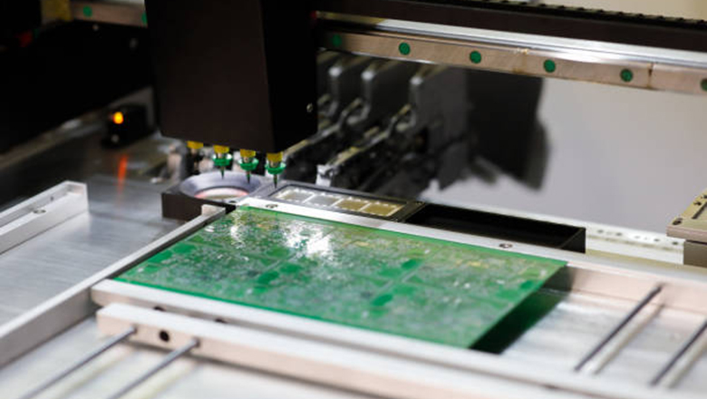
- Method:The machine first automatically inserts the component pins into the circuit board (automatic insertion), and then allows the board to pass through a wave of molten tin, completing all the solder joints in one go.
- Advantages:It has high consistency, is very fast in mass production, and can also save labor.
- Drawback:The initial equipment investment cost is relatively high, making it unsuitable for small-batch production or complex boards that require manual adjustment.
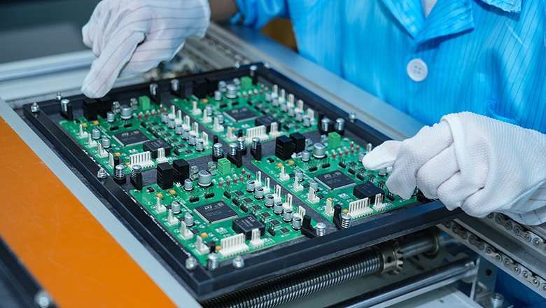
In the modern PCB industry, many companies combine surface mount and through-hole assembly to leverage the speed of SMT for most components, while reserving through-hole assembly for connectors, power parts, and mechanical mountings.
Prototyping, Low-Volume, and Industrial Applications
Through-hole PCB assembly remains the gold standard in particular scenarios:
- Prototyping:When making a board for the first time or when it is operated by an inexperienced engineer, the first consideration should be to operate a board with through holes.
- Low-Volume Runs:Compared with speed, flexibility and solution flexibility are more valued. It is more reliable to choose hand welding.
- Harsh Industrial Environments:For heavy industry, military industry, aerospace and other types of boards, they need to be firmly installed and resistant to vibration. Through-hole boards are the first choice.
- DIY/Maker Projects:Teaching kits, self-made synthesizers, robots, and the maintenance of old equipment all basically use through holes. Soldering by yourself is the first choice.
Advanced Assembly: Hybrid and Complex Boards
Hybrid Assembly Techniques: Nowadays, many high-end PCBS use a combination of through-hole and SMT. Let’s take a look at the differences between the two processes.
- Mounting:For components that require a lot of effort, such as power supplies and interfaces, through holes are usually used and welded firmly. The signal processing or microcontroller part will be entrusted to SMT, which takes up less space and can accommodate more functions.
- Soldering:In terms of the process, SMT components are usually pasted first, then reflow soldered, and then through-hole components are inserted. Wave soldering or manual repair soldering is used – in this way, the two processes do not interfere with each other and the efficiency is also high.
FAQs on Through-Hole PCB Assembly
Q: How do I decide between through-hole assembly and SMT?
A: If you want something sturdy, capable of withstanding large currents, easy to maintain, or are conducting teaching experiments – then use through holes. If you are looking for small boards, the ability to produce automatically and high speed, then leave it to SMT.
Q: What is the main advantage of through-hole PCB assembly for beginners?
A: The components are large, easy to hold by hand, have a high fault tolerance rate, and are also easy to disassemble if they are soldered incorrectly. When troubleshooting problems, I can use a multimeter to check each point accurately, which is very convenient.
Q: Can through-hole and SMT components be used on the same PCB?
A: Sure, this is called hybrid assembly. It’s quite common on both prototype boards and mass production boards. It’s about complementing each other’s strengths.
Q: Why is soldering iron temperature control important?
A: If it is too low, the solder joints will be dark and not firm (cold soldering); if it is too high, it is easy to heat up the pads or burn out the components. It depends on what kind of solder wire you use. Generally, set it to a little over 300℃ and feel it while soldering.
Q: What are the most important steps in through-hole PCB assembly?
A:When laying out the board, sufficient allowance should be left, and the sizes of the holes and pads must be correct. The drilling should be clean and the components should be inserted to the bottom. When soldering, don’t be in a hurry. Let the solder flow through naturally and the solder joints be full. If each step is done properly, the board will naturally be stable.
Conclusion
Through-hole Technology still holds an irreplaceable position in the field of electronic manufacturing, especially excelling in application scenarios that emphasize mechanical strength, maintainability and teaching applicability. This article comprehensively reviews the key links in the assembly of through-hole PCBS – from the selection of assembly methods to the scenarios in which through-hole technology is superior to surface mount technology (SMT), providing readers with a basis for practice.
Whether you are a student soldering your first circuit, an engineer designing industrial-grade PCBS, or a project leader preparing to make small-batch prototypes, the principles and advantages contained in through-hole assembly still have significant reference value. This process achieves a stable mechanical bond by inserting component leads into pad holes, welding on the opposite side of the board, and ensuring that each solder joint forms a reliable electrical connection, which can withstand vibration, temperature changes and physical stress. For this reason, it is not only widely used in prototype verification and maintenance processes, but also plays a crucial role in fields with extremely high reliability requirements such as industrial control, automotive electronics, aerospace, and military equipment.
Optimizing Your Through-Hole Assembly Projects
After delving deeply into this industry, you will find that truly successful projects often combine the use of both new and old technologies. For instance, when it comes to power supply or places that need to be fixed, use through holes – they are sturdy. The signal processing part is handed over to SMT – saving space and taking advantage of each other’s strengths. The technical manifestation of through-holes, from the initial board layout and drilling, to component insertion, welding and inspection, each step of operation will ultimately be directly reflected in the performance of the board.
Recap of Key Success Factors:
- Meticulously plan your PCB layout:When laying out the board, the size of the drill holes and the position of the solder pads are all designed in accordance with the original manual to ensure the principle is reasonable. This is the first step in laying out the board.
- Focus on quality soldering:The soldering iron should be clean and temperature-controlled. The amount of solder should be appropriate, allowing it to flow out along the pins and pads and solder thoroughly. After welding, pick it up and check the back. Only when it is full and smooth can it be qualified.
- Inspect as you assemble:Remember to prevent cold soldering. If there is solder connection between the pins, it should be dealt with as soon as possible. Finally, test with a multimeter.
- Leverage automated insertion and wave soldering:The efficiency of large-scale production of automatic insertion combined with wave soldering is the highest. For small batches or experimental operations, please choose hand soldering. It can break down every detail and allow you to experience the process from nothing to something.


