Introduction: Why are Circuit Boards Particularly Important in Modern Technology?
Every machine that can demonstrate technological capabilities has a circuit board. All the technicial machine and high-tech and high-quality medical equipment are all composed and circuit boards work, which represent the core of technology. Therefore, we will discuss what a circuit board is and how it works.
Circuit boards are complex, and their structure allows electrical signals to flow between different components. Each board has its own components that enable devices to operate effectively. Computer circuit boards, commonly known as motherboards, are particularly important in information technology as they can support CPUs, memory, and other devices that can operate with each other. The technology, design, and materials behind PCBs are the foundation of modern technological society.
What Is a Printed Circuit Board (PCB)?
A printed circuit board, or PCB for short, is really just a flat board made from stuff that doesn’t conduct electricity — usually fiberglass or a type of epoxy resin mixed with glass fibers. You solder all kinds of electronic components onto this board, and together with the copper traces on the board, they make up a working circuit. In the past, if you wanted to design a product (its electronic prototype), you generally had two choices: either to connect everything point-to-point, or to place the components on the circuit board. However, with the gradual development of technology, these are not enough to meet people’s needs. Everyone has begun to realize that they need better products and higher technological content to raise standards.
Anatomy of a Printed Circuit Board
- Base Material: The board is typically made of fiberglass (FR4) or another non-conductive material, providing strength and insulation.
- Layer of Copper: PCBs are made by laminating one or more thin layers of copper onto the board. The copper is then etched away behind the desired circuit pattern to form traces that form the circuit.
- Solder Mask: A protective layer covering the copper traces except where soldering is required.
- Silkscreen: The topmost layer features printed text and symbols, showing placement and orientation for various components on the board.
Understanding PCB Construction
| Layer | Material | Function |
| Substrate | Fiberglass or composite epoxy (FR4) | Mechanical stability; electrical insulation |
| Copper | Pure copper | Electrical connections; flow of electrical energy |
| Solder Mask | Polymer resin | Prevents shorts, oxidation; makes board green/blue/etc |
| Silkscreen | Epoxy ink | Labels: shows component positions on the board |
| Components | Resistors, capacitors, ICs, etc. | Work together to perform electrical circuit functions |
Did You Know?
A flat board made of non-conductive material, etched and drilled with precision, is the platform upon which modern electronics are assembled. It’s the invisible stage where the magic of digital life happens!
How Are PCBs Made? (How to Make a Circuit Board)
Modern circuit board manufacturing is a multi-step process that transforms a conceptual design into a working, robust, and reliable structure.
Step-by-Step: Circuit Board Manufacturing
- Designing the Circuit Pattern
- Create a schematic diagram using CAD tools, defining electrical connections.
- Preparing the Physical Layout
- The layout of the circuit board means placing the traces, pads, and holes in the board based on the schematic. This layout determines how components work together and form a complete circuit.
- Printing/Transferring the Design
- A printed board image is applied onto the surface of the board—this can be done photolithographically for high precision.
- Behind the desired circuit pattern, copper not covered by resist is etched away, leaving copper traces that form the electrical pathways.
- Holes in the board are made both for mounting components (through-hole technology) and to create vias that connect layers in a multilayer board.
- Plating, Solder Mask, and Silkscreen
- Holes and vias are plated with copper to ensure connectivity, a solder mask is added, and the silkscreen is printed.
- Soldering and Board Assembly
- Different components are then soldered onto the board using reflow ovens for SMDs or hand/wave soldering for through-hole parts. Components are placed on the board with either manual or automated (pick-and-place) machines.
- Inspection and Testing
- There are generally three types of testing: using AOI, conducting voltage and current tests with equipment, or manually checking whether all components on the circuit board are connected correctly.
Types of PCBs and Types of Printed Circuit Boards
There are several types of PCBs and each serves different requirements of the circuit and application.
Basic Types of PCBs
| PCB Type | Description | Common Use |
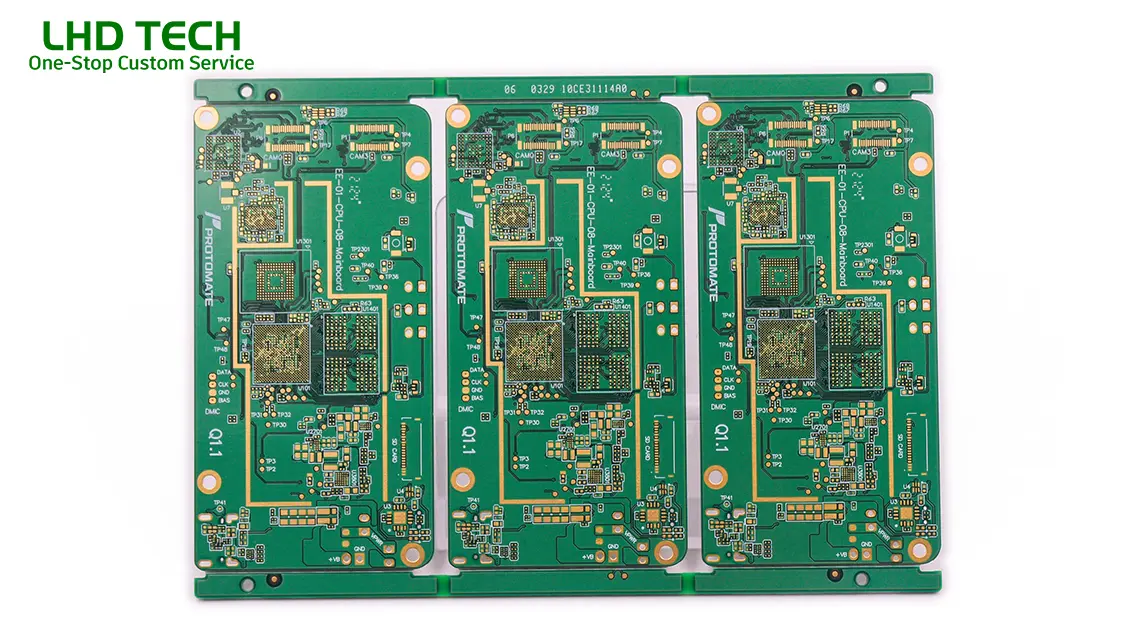
| Single-sided boards | Copper on one side only, components on top | Simple electronics, hobby projects |
| Double-sided boards | Copper and components on both sides | Power supplies, more complex gadgets |
| Multilayer board | Multiple copper layers separated by insulation | Computer circuit boards, smartphones, routers |
| Rigid PCB | Solid, inflexible (most common) | TVs, desktops, peripherals |
| Flex PCB | Made with flexible material (polyimide) | Wearables, foldables, medical catheters |
| Rigid-flex PCB | Combination for specific requirements | Medical, aerospace, advanced consumer devices |
Types of Printed Circuit Boards
| Requirement | Best PCB Type(s) | Example |
| High reliability | Multilayer, rigid-flex | Computer circuit boards, aerospace |
| Compact design | Multilayer, flex, HDI (high-density interconnect) | Smartphones, tablets, IoT devices |
| Simple/repairable | Single-sided, double-sided | Audio amps, appliances, learning kits |
| High current | Heavy copper, double-sided | Power converters, EV chargers |
Key Components Placed on the Board: What Makes the Circuit Board Work?
The heart of the functioning of electronic devices is how different components on the board interact via electrical connections. The printed circuit board provides a platform for various components that are soldered onto the board.
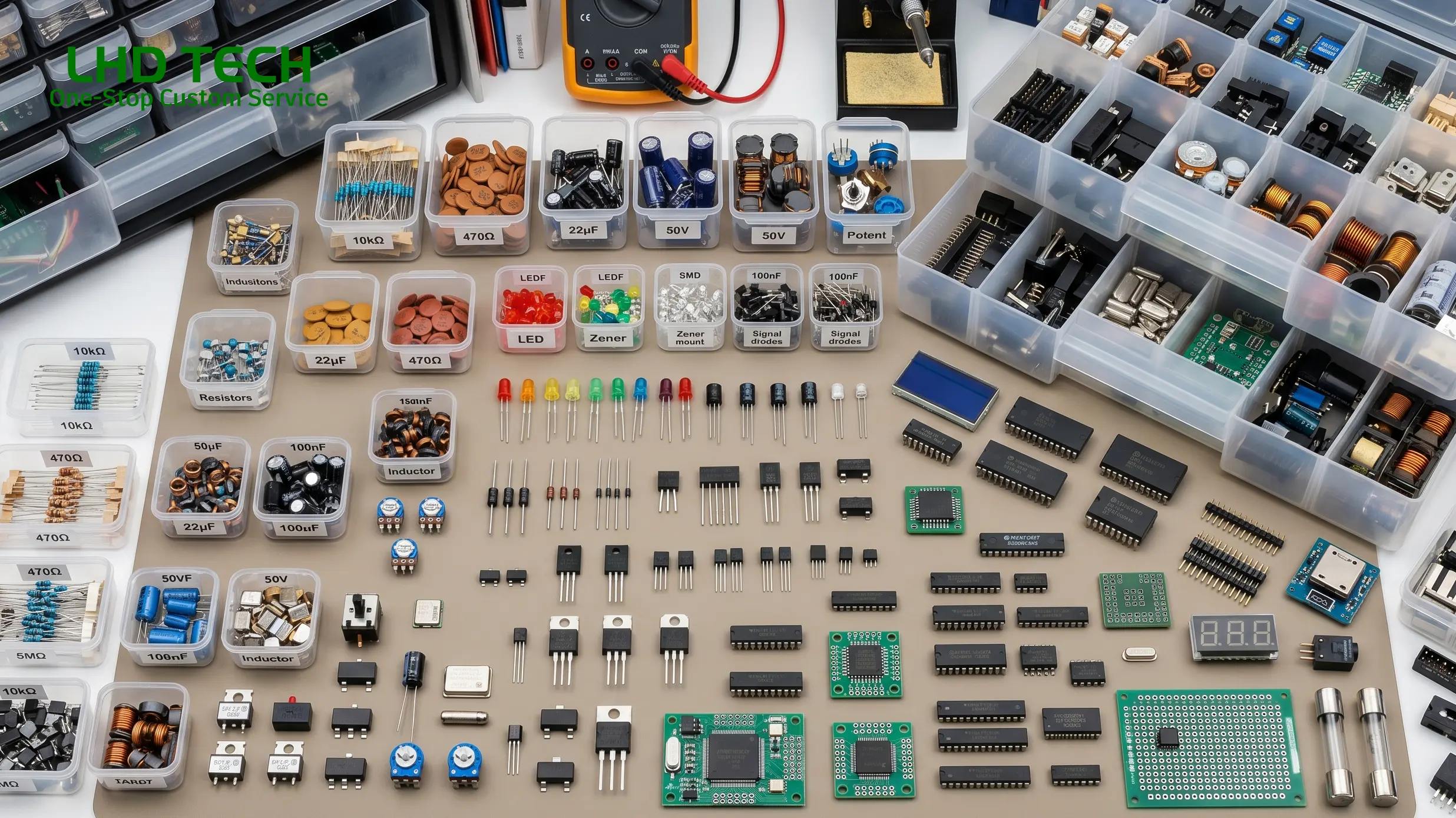
Common Components on Every Circuit Board
- Resistors: Basically, they just block current. Put a certain resistance value in, and you get a certain amount of current flowing. They also split voltage — like taking one voltage and cutting it in half.
- Capacitors: Kinda like tiny buckets. They store a little bit of charge and then let it out when needed. You see them everywhere for cleaning up noisy signals or making small time delays. That little cap next to a power pin? That’s exactly what it does.
- Inductors: You don’t see these as often, but they still show up. They store energy in a magnetic field and mostly get used to filter out high‑frequency noise. Sometimes they work together with capacitors for power filtering.
- Diodes: One‑way street for current. Current can go forward but not backward, so they’re great for reverse‑voltage protection. That little black part right next to your power connector? Probably a diode.
- Transistors: These are the workhorses — switches and amplifiers. On any computer board or complex circuit, you can’t do much without them. A tiny current can control a much bigger one, or you can use one to boost a weak signal.
- Integrated Circuits (ICs): A tiny black chip that packs thousands or even millions of transistors, resistors, and other stuff inside. CPUs, memory chips, controllers — those are all ICs. It’s fair to call them the brains of the board.
- Connectors & Headers: These are the board’s way to talk to the outside world. Plug in external devices, hook up power, connect to another board — all through these. Without connectors, your circuit is just an island.
- Oscillators & Crystals: They provide the beat, the clock signal. If you want your CPU, memory, and other chips to stay in sync and not mess up, you need one of these. Usually a little metal can or a small crystal part.
- Sensors & Switches: These let the circuit interact with the real world. Temperature sensors, light sensors, push‑buttons — all of them. You press a button, and the board knows you did something.
How are components coordinated?
For acircuit board to function properly, simply stacking parts together is not enough. When designing, engineers carefully arrange the positions of resistors, capacitors, chips, and other components on the board – not randomly, but based on how the signals go and where they come from. The purpose of doing this is very direct: to make the electrical signal run smoothly, reduce energy loss, and try to avoid mutual interference between signals (which we often refer to as crosstalk).
How can the electricity go and how can the data be transmitted? It all depends on the “traces” on the board. Simply put, it is the thin lines etched on the copper foil, which are equivalent to small paths or highways in the circuit. The signal runs steadily and reliably along these copper wires from one end to the other.
After the entire board design is completed and all components are soldered, each part begins to perform its own duties. Some are responsible for amplifying sound, some are responsible for processing data in computers, and some coordinate critical instructions that can save lives in medical equipment. The different combinations of components determine what this circuit board can do – whether it’s a small amplifier, running a CPU, or becoming the main control board in a ventilator.
Designing a Circuit Board: From Schematic to Complete Circuit
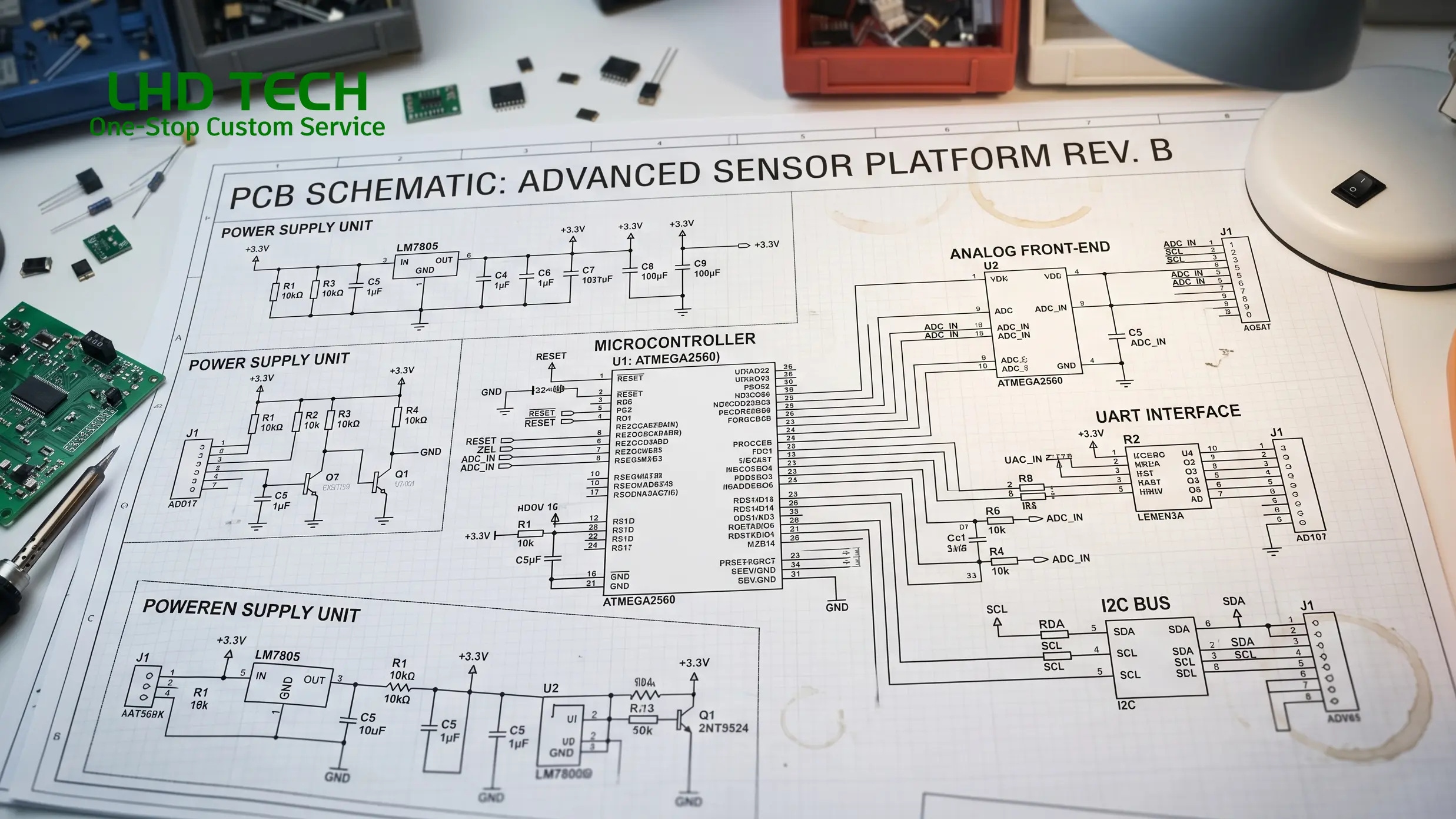
Designing a circuit board is a strategic, multistage engineering process. The reliability of the circuit board depends as much on the logic of the electronic circuit as the physical pattern of the layer of copper on a flat board.
Steps in Circuit Board Design
Schematic Creation
- Using CAD (Computer-Aided Design) tools, engineers draw a symbolic map of all electrical signals and components.
- A well-designed schematic is readable, separates functional blocks, and clearly designates how components work together.
Board Layout
- The layout of the circuit board transforms the schematic into the physical arrangement of traces, pads, and holes in the board, considering electromagnetic compatibility and mechanical requirements.
- Components are placed on the board for efficient signal flow, heat management, and ease of manufacture.
Routing Traces
- Careful trace routing ensures the flow of electrical signals without interference. High-speed or sensitive circuits may require special patterns, extra ground layers, or impedance control.
- Vias connect different layers in a multilayer board; blind/buried vias save space and enhance performance in HDI boards.
Design for Manufacturability (DFM)
- Design choices must match the capabilities of circuit board manufacturing. Traces can’t be too thin, holes in the board must be the right size, and spacing should allow for reliable soldering.
Simulation and Verification
- Electrical simulations and design rule checks confirm closed circuit integrity, signal integrity, and rule compliance before fabrication.
Advice for New Designers:
- Start with a single-sided board or breadboard for simple circuits.
- Use clear component labels (reference designators) and silkscreen markings to make troubleshooting easier later.
- Remember: How the board is designed will impact not only how well it functions, but also how easy it is to repair or upgrade.
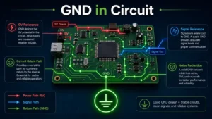
The Flow of Electrical Signals: How Circuit Boards Work
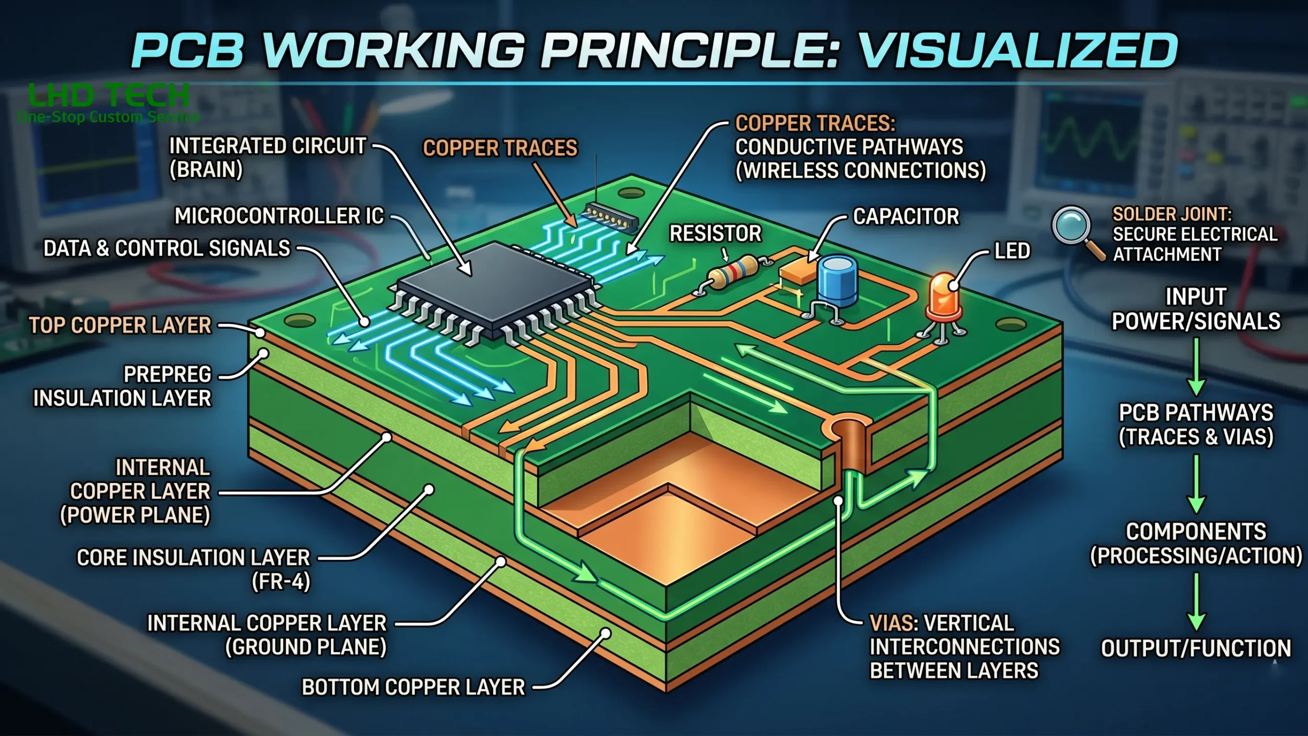
Understanding how electrical signals move and how a circuit board works is essential for both beginners and pros.
Step-by-Step: Flow of Electrical Energy
- Power Input:
- Voltage is supplied via connectors or soldered terminals on one side of the board.
- Distribution:
- Copper traces distribute electrical energy from the power supply or battery across the board, feeding each component according to its voltage/current needs.
- Signal Control and Processing:
- Integrated circuits, transistors, and supporting components direct the flow of electrical signals according to the requirements of the circuit.
- Logic circuits on computer circuit boards process data, while amplifiers process analog signals in audio gear.
- Modulation and Protection:
- Diodes prevent reverse current, voltage regulators stabilize supply, and capacitors filter out electrical noise to ensure a closed circuit free from spurious signals.
- Output and Feedback:
- The processed output—be it a displayed image, audio amplification, or network communication—relies on the seamless function of all components integrated via traces on the board.
Common Signal Flow on Computer Circuit Boards
| Signal Flow Stage | Function | Example on Board |
| Input | Receives user or sensor signal | Keyboard input on computer board |
| Processing | Logic, calculation, or transformation | CPU, GPU, or microcontroller |
| Storage | Retains data or state | RAM or flash chip |
| Distribution | Routes processed data/power | Data bus, power rails |
| Output | Displays, actuates, communicates | HDMI/display output, USB data |
Engineering Insight
Every trace on a circuit board, every via, and every layer of copper is purpose-built to ensure that the flow of electrical signals reaches the right component at precisely the right time. Without circuit boards streamlining and protecting these signals, modern electronics simply wouldn’t function.
PCBs in Electronics: Computer Circuit Boards and More
PCBs are essential in electronics and electrical engineering—from everyday gadgets to life-critical equipment and beyond.
Where Circuit Boards Are Used
- Computer circuit boards in PCs, servers, and laptops. The motherboard acts as the ultimate platform, interfacing CPU, memory, graphics, and IO—all essential for the flow of electrical signals in computer systems.
- Embedded electronics (IoT devices, smart appliances, automotive ECUs).
- Medical electronics (diagnostics, implants, monitoring devices), which demand unmatched reliability of the circuit board.
- Telecommunications, industrial automation, robotics, and aerospace, each with their own requirements for robustness, multi-layer reliability, and form factor.
Electronic Devices Would Not Function Without Circuit Boards
Without circuit boards, electronic device reliability and miniaturization would not be possible. PCBs are made to fit the exact requirements of the circuit and device, whether it’s a wearable tracker or a mainframe server. The tailored arrangement of various components on the board, the perfect routing of traces, and mastering the technique of board is designed for specific tasks—that’s what enables today’s electronics to outperform every previous generation.
Troubleshooting, Reliability, and Safety in Circuit Board Technology
Proper troubleshooting and a focus on safety and reliability are non-negotiable parts of working with the flow of electrical signals on printed boards and complex circuit designs.
Reliability Factors
- Quality of Board Material: Inferior or non-standard substrate can degrade, warp, or lose insulation—a primary reason for circuit failure in harsh environments.
- Trace Design: Incorrect width or layout can cause overheating, EMI, or short circuits.
- Component Soldering: Poor soldering leads to cold joints, open circuits, or unreliable connections (especially on the underside of the board).
- Environmental Protection: Conformal coating and proper enclosure help prevent moisture, dust, and mechanical damage.
Safety Essentials
Electrical energy on a circuit board—especially mains-powered or high-current designs—can be hazardous. Always:
- Work on unpowered boards whenever possible.
- Discharge capacitors (they can store and release electrical energy long after power is off).
- Use ESD protection (wrist straps, grounded mats) to avoid static damage to sensitive devices.
Troubleshooting Tips
- Visual Inspection: Look for burnt traces, broken or lifted pads, and bad solder joints.
- Use a Multimeter: Check continuity, look for short circuits, and verify component function.
- Test Points: Use built-in test points for easy monitoring of voltage and signal on the board.
- Thermal Imaging: Find overheating components fast—preventing catastrophic failures.
- Functional Substitution: For computer circuit boards, swapping known-good modules (RAM, GPU, etc.) narrows down problems quickly.
Modern Trends in Circuit Board Manufacturing and Electronics
Circuit board technology is continuously evolving to meet the growing demands of complex circuit designs in modern electronics.
Key Innovations
- HDI (High-Density Interconnect) PCBs: Allow more traces and connections in a smaller space, essential for smartphones and computer circuit boards.
- Flexible and Rigid-Flex PCBs: These adapt to unconventional shapes and movements, like wearables or foldable screens.
- Sustainable Materials: Eco-friendly substrates and lead-free solder are making PCBs greener.
- 3D Printed Boards: Digital fabrication is enabling rapid prototyping and production for experimental and customized electronics.
- Smart PCBs: With sensors, wireless modules, or embedded microcontrollers directly in board material—“smart” boards are the next frontier.
Frequently Asked Questions About Circuit Boards
Q: What is the difference between a PCB and a computer board?
A PCB refers to any printed circuit board—however, a “computer board” (like a motherboard or graphics card) is a specific type of multilayer PCB that connects, controls, and powers all the core computer components.
Q: How does the layout of the circuit board affect performance?
The layout directly impacts the flow of electrical signals, signal integrity, EMI, heat dissipation, and, ultimately, the reliability of the circuit board. Poor layout can lead to noisy signals, missed connections, or even catastrophic performance issues. For example, on advanced computer circuit boards, high-speed traces for memory or processor signals must be routed to precise lengths and distances to maintain synchronization. The way a board is designed—trace width, via size, pad placement, and copper layer stackup—determines not only function and speed, but also longevity and ease of troubleshooting.
Q: What are the main differences between single-sided boards and multilayer boards?
- Single-sided boards have copper traces on just one side of the board, with all components placed on the board’s top. They are typically made for simpler electronic devices, often in hobby projects or older appliances.
- Multilayer boards contain several layers of copper traces sandwiched between layers of board material. This enables complex circuit designs needed for modern electronics, such as smartphones, advanced graphics cards, or any application with dense electronic circuit requirements. Multilayer boards offer better electrical connections, improved flow of electrical signals, and reduced electromagnetic interference.
Q: Do all PCBs use the same board material?
No. While FR4 fiberglass is the most common, some PCBs are made of polyimide for flexibility, ceramic for high temperature or high-frequency performance, or even specialized composites for particular applications in aerospace or medical electronics. The selected board material must match the electrical, mechanical, and thermal requirements of the circuit and its end use.
Q: How are components soldered onto the board?
Components are either soldered by hand—for small runs, repairs, or prototypes—or by automated pick-and-place and reflow ovens in modern factories. Soldering can occur on one side of the board or both, depending on whether it’s a single-sided, double-sided, or multilayer board. Surface of the board assembly is often handled entirely by robots for accuracy and productivity, especially for complex or high-volume production.
Q: What does it mean when we talk about the flow of electrical signals in a closed circuit?
A closed circuit means that electrical signals and energy can travel from the source, through various components on the board, performing designed functions, and then return to the source without interruption. This completes the circuit. If there’s a break (an open circuit), or if signals go astray (a short circuit), the board can’t work as intended.
Q: Why are circuit boards essential to the functioning of electronic devices?
Circuit boards are essential components because they physically support and electrically connect all the different pieces—resistors, capacitors, chips, and more—so these pieces can work together seamlessly. The reliability of the circuit board is what makes cell phones, computers, medical monitors, vehicles, and even space probes operate dependably, 24/7.
Q: Can I make a circuit board at home?
Yes! DIY PCB kits and digital fabrication methods allow anyone to design and etch a simple printed board for learning or prototyping. Most hobbyists start with single-sided boards made of copper-clad FR4—they draw the desired circuit pattern using resist pens or toner-transfer, etch away the unwanted copper behind the pattern, drill holes in the board, and solder components. This hands-on experience underscores how PCBs are made and strengthens understanding of electronics and electrical engineering basics.
Conclusion: Why Circuit Boards Are Essential Components
In the world of electronics and electrical engineering, circuit boards are made to be the unsung heroes bridging theoretical designs and working technology. Every complete circuit—from simple LED flashers to computer circuit boards in supercomputers—relies on a board made of non-conductive substrates and layers of copper, connecting various components to the board in precise patterns that control the flow of electrical signals and energy.
Without circuit boards, modern electronic devices as we know them simply wouldn’t exist. The reliability of the circuit board, determined by how the board is designed, soldered, and tested, is at the heart of dependable computers, efficient vehicles, powerful medical devices, home automation, and so much more. Today, with advances in digital fabrication and manufacturing, circuit board technology continues to evolve—chasing the ever-advancing requirements of the circuit and demands for miniaturization, flexibility, and resilience.
Whether you’re learning how to make a circuit board, designing a complex multilayer electronic circuit, or troubleshooting a computer board, remember: the story of electronics is written in copper and resin, one trace and one component at a time.