Introduction: PCB, AC, DC & How to Use AC in a PCB
A printed circuit board (PCB) include the foundation for all electronics, power supplies, and digital systems. No matter you’re dealing with direct current (DC) in your DC circuits or alternating current (AC) in an AC circuit, we can understanding the safely and optimally through use AC in a PCB is very important for stability and reliability. Especially In high power environments and devices, they all need to handle both types of current, manag the difference between AC and DC is an basic skill for the designers who is working on electronic circuit boards.
Why is this important?
Not like DC, its current flows in a single direction, AC current changes direction continuously, it will cause complex trace design, thermal management, and need to practices for handling both conductive and capacitive effects. The boards are designed in order to meet these challenges so they can carry high current safely , insulate sensitive electronics, then keep components on the board in safe temperatures. If you’re designing circuits for industrial power supplies, smart home systems, or sensitive analog electronics, we can see how to use AC in a PCB is necessary.
What is Alternating Current (AC)? The Basics of Current in Circuit Boards
AC and Current Flow
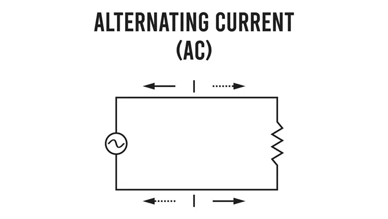
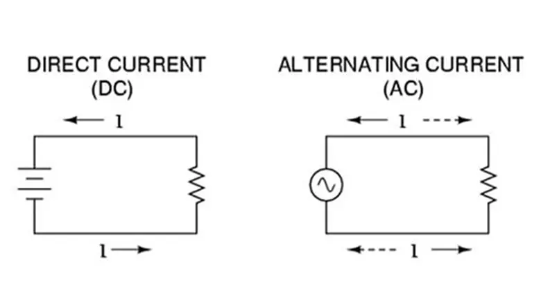
Alternating current (AC) describes any electrical current that changes direction periodically—most commonly in a sinusoidal wave form. The voltage and current both shift from positive to negative, typically at 50 or 60Hz for power systems around the world.
- Key differences: Unlike DC current, which flows only one way, AC can be used for efficient transmission of power and is transformed easily for electrical systems—all you need is a transformer to step the voltage up or down.
- Current flow in AC circuits is more complex, with the path of least resistance determined by both resistance, capacitive, and inductive properties.
- PCB design for AC signals—especially at high frequency—means accounting for these rapidly changing directions and the associated electromagnetic effects.
Table: AC vs. DC Key Properties
| Property | AC (Alternating Current) | DC (Direct Current) |
| Direction | Reverses; sinusoidal, square, etc. | Unidirectional; constant |
| Use in PCB | Power supply input, inverters, some audio/comms | Logic, MCUs, most on-board circuits |
| Circuit Boards | Special trace design, insulation, and EMI controls | Standard, denser trace packing allowed |
| Inductive/Capa. Effects | Strong, must be managed | Lesser, but present in high-speed DC circuits |
AC and DC: Differences & Why They Matter for PCB Circuit Design
The Difference Between AC and DC in Circuit Boards
For PCB designers, the main differences between AC and DC is to trace a design, current loads, insulation distance, and EMI susceptibility:
- DC current is simply; it only flows from one point to another, mak the layout, power planes, and thermal management.
- AC signals and power introduce capacibiliy and inductive challenges (impedance, voltage, and phase shifts) its influence how traces and components must be placed.
Scope of AC in Circuit Boards
- Use of alternating current is common in the input sections of power supplies, motor controllers, and audio electronics.
- Boards are designed with wider spacing and thicker copper for AC traces to accommodate higher voltages, changing current, and increased heat generation. They may require specialized insulating materials and conformal coatings.
AC or DC: Which Current Do Most Circuit Boards Use?
Most circuit boards use DC inside board-level electronic circuits. Power supplies convert AC input into one or more DC voltages for MCUs, logic, and analog functions. This conversion happens through a series of steps that ensure stability and reliability.
Where AC vs. DC Are Used in a Typical System
| Section | Current Type | Role |
| Mains Input | AC | Raw power, requires conversion |
| Power Adapter Section | AC/DC | Converts and isolates AC to multiple DC rails |
| Internal (MCU, Digital) | DC | Stable voltage for chips, sensors, comms |
| High-Power Switching | AC (& DC) | Relays, triacs, or MOSFETs switch AC or regulated DC loads |
| Communication/Signal | AC & DC | Audio, RF, modulation/demodulation, clock, and bias circuits |
How to Use AC in a PCB: Trace Design, Placement, and Devices That Need AC

Key Design Principles for Using AC in a PCB
If you need to use AC in a PCB, we need to pay attention the following design aspects:
- Trace Design: Use wider traces for high current and high voltage to prevent excessive heating (thermal buildup) and arcing. Refer to IPC-2221 standards for spacing based on voltage.
- Current Loads: AC traces, unlike DC, must be sized for both RMS (average) and peak current loads. The designers have to use a copper weights on 2oz or more.
- Thermal Management: Integrate heat sinks and thermal hole under components is rectifiers, voltage regulators, transformers, etc.
- Placement of Components: Position of input AC filte components (like common-mode chokes, EMI filters) close to the AC point, sensitive MCU or signal position.
- Insulate: To separate AC and DC zones clearly, both physically and with ground pours in our PCB layout tool (for example, Altium).
Devices That Need AC Directly on the PCB
- Motors (washing machines, industrial, HVAC)
- Inverters (solar or backup systems)
- LED drivers (the direct, dimmable n lighting)
- Audio amplifiers (where both AC signals and power are present)
- Smart IoT relays and switches requiring AC control and isolation
Conversion of AC: How AC to DC Happens on Circuit Boards
In nowadays the modern electronic board, the conversion of AC to DC is a basic process. This conversion allows the designers use mains AC power (which changes direction and voltage) to generate the stable, regulated direct current (DC current) for sensitive electronic circuits.
Step-by-Step: AC to DC in a Power Supply
AC Input and Surge Protection:
- Devices receive alternating current via the power connector.
- Surge protector or Metal Oxide Varistors protect sensitive the components from harmful transients.
Transformer:
- Steps down (or set up, in rare cases) the voltage.
- Provides electrical isolation, reducingthe
Rectification:
- A diode bridge (full-wave rectifier) turns the AC’s rapidlydirection in a pulsating, unidirectional current.
- Common rectifier components: 1N4007 diodes, KBPC diodes.
Smoothing Filter:
- Large-value capacitors (electrolytic) and sometimes inductors smooth out the voltage ripple, making the signal more DC-like.
- Ripple factor is minimized so downstream circuits get the stability they need.
Voltage Regulation:
- ICs like 7805 or LM317 voltage regulators further filter and clamp the DC voltage to precise levels (e.g., 5V, 3.3V, 12V).
- These regulators provide short-circuit and over-temperature protection as part of the thermal management strategy.
Illustrative Table: AC to DC Conversion
| Step | Component | Purpose |
| Surge Protection | MOV, fuse | Blocks high-voltage spikes |
| Isolation & Step-down | Transformer | Reduces/increases AC voltage, provides isolation |
| Rectification | Diode bridge | Converts AC to pulsating DC |
| Filtering | Capacitor, inductor | Smooths ripple, reduces noise |
| Regulation | Voltage regulator IC | Output is precise, stable DC for electronics |
Common Pitfalls in AC to DC Design
- Undersized Capacitors: Lead to high ripple and instability.
- Inadequate Heat Sinks: Can cause regulators or rectifiers to overheat.
- Insufficient Trace Width: Results in excessive voltage drop and possible burning of PCB traces under high current loads.
- Poor Placement of Components: If high-voltage AC traces intersect with low-voltage DC circuits, this will exacerbate electromagnetic interference (EMI) and may also give rise to unsafe conditions.
Aspects of PCB Design: Using AC, Current Loads, Trace Design, and Thermal Management

PCB Traces: Managing Current Flow
- Trace width is calculated on the max amount of people’s expected, the permissible temperature will rise, and the thickness of the copper that we mainly Online calculators and IPC-2221 guidelines are invaluable.
- For high-power AC circuits, we need consider double-sided ormulti-layer boards with extra copper pours on internal or external layers (“power planes”) in order to dissipate heat and distribute current flow.
- Thermal holes under hot components (rectifiers, voltage regulators, power transistors) link the heat-generating pads to larger ground planes, it can improving thermal management.
Placement of Components and Path of Least Resistance
- Place high current and high voltage components close together and near the input edge. This reduces trace length and associated voltage drop.
- Designers must confirm that the path between input (for AC) and output (to DC rails) follows the shortest, safest, and most thermally balanced route.
- Proper component groupingalso aids in inspection, service, and EMI containment.
Trace Design Tips for AC Circuits
- Route AC signals with generous clearance to reduce risk.
- Avoid parallel runs of high-frequency AC tracesto sensitive signal lines, as this induces unwanted coupling.
- Use guard traces or ground pours between AC and DC regions for added insulation.
Thermal Management is Critical
- Metal-core PCBs or heavy-copper boards are ideal for high-power supplyand lighting drivers.
- Use of forced-air cooling is commonin daily life.
- Heat sinks and thermal vias help safeguard sensitive components, it can ensuring the board meets the demands of high current loads.
Applications: High Power, Electronics, and Devices That Use AC in PCBs
Where AC Can Be Used—and Why
- AC power supplies in industrial machines, telecommunication base stations, and data centers leverage for reliability and heat management.
- LED lighting drivers use AC input, often routed across both sides of the PCB for optimal current distribution.
- Motor controllers (industrial, appliance, automotive) rely on careful separation of AC and DC paths to prevent unintended operation and electrical noise.
- Inverters in solar PV systems, battery backup units, and smart grid applications are complex AC circuit boards, often with dual-layer high-copper construction and precise trace design.
Case Example: Motor Controller PCB
A washing machine PCB receives AC from the wall outlet, with traces carrying up to 10A RMS current. The board features:
- Two-ounce copper for power traces.
- Creepage gaps >5mm between the AC mains and low-voltage logic.
- Snubber networks and varistors for EM noise suppression.
- MCU positioned far from AC paths, insulated by ground pours and optoisolators.
How Boards Are Designed for Stability and Reliability
- Devices that need AC (e.g., HVAC, power tools, EV chargers) for long life by insuring that PCB traces, we can withstand surge currents and repeated thermal cycling.
- Proper use of thermal management (heat sinks, via stitching, power planes) it can ensures even high current loads and don’t damage traces electronic circuits over time.
Dealing with AC: Electromagnetic Interference, Capacitive, and Inductive Effects
Managing Electromagnetic Interference (EMI)
- Dealing with AC requires extensive EMI precautions. Quick current changed can radiate signals, interfere with wireless, or trip nearby logic.
- Capacitive and Inductive Coupling: AC signals on adjacent traces usually induce unwanted voltages—especially in high-speed, high-frequency, and alsor high-power designs.
- Use EMI filters, normalmode chokes, and carefully placed bypass capacitors to combat both radiated and conducted EMI.
Design Strategies:
- Shield AC entry points in metal enclosures or use Faraday cages around critical areas.
- Place input filters near the AC inlet.
- Maintain separate ground paths for power/current return and low-level signal reference to avoid ground loops.
Case Study: Audio Amplifier PCB
High-fidelity audio amplifiers often have both AC power for amplification and delicate DC rails for analog circuits. Designers:
- Physically isolate AC mains sections.
- Use thick ground traces/pours for AC return.
- Filter power to analog sections with a combination of inductors and capacitors to make the signal as clean as possible.
Best Practices: PCB Traces, Placement of Components, and Current Flow Stability
Best Practice Checklist
- Wide, robust traces for high current paths—calculate for both RMS and surge values.
- Double-sided boards for balanced current distribution; use traces and components on both sides where needed.
- Insulate using slots, keepout areas, and high-CTI base materials.
- Segregate power supplies, AC, and DC areas clearly, using placement and silkscreen markings.
- Thermal vias and heat sinks under all power semiconductors and high dissipation resistors or inducto.
- Careful placement of components: keep voltage regular, rectifiers, and filtering capacitors close together for ripple and noise mini.
- Always check amount of current and adjust trace and copper pour sizes to prevent overheating or voltage drop.
- Model current flow using field solvers and simulation, especially in Altium or industry-leading EDA tools.
Frequently Asked Questions: Difference Between AC and DC, Altium, Insulate, and More
What is the core difference between AC and DC on a PCB?
AC changes direction and is more likely to induce EMI and heat, requiring careful trace spacing and insulation. DC flows in one direction and is easier to route densely.
How do I insulate AC traces from DC and logic circuits?
Use high-quality base materials, keepout regions, routing on separate PCB layers, and optoisolation for signals that cross power domains.
When should I use a multi-layer board in AC applications?
Any time you have high current, need to meet strict EMI or heat dissipation requirements, or have a complex design needing robust power planes.
What simulation tools help optimize trace design and current flow?
Altium Designer, Mentor Graphics, and Eagle each offer current density, thermal, and EMI simulation features, it is very important for complex power and mixed-signal boards.
Can AC Be Used for Signal Transmission on a PCB?
Yes, AC signals are usually used to carry the information such as audio, video, data, and clock signals across PCBs. Maintaining signal integrity is critical, particularly at high frequencies. We can optimized the trace layouts toto reduce reflections and signal loss; for high speed AC signals including HDMI, USB, and RF signals, controlled impedance, short trace routes, and appropriate termination resistors are essential.
How Do Inductors and Capacitors Play a Role with AC on PCBs?
- Inductors oppose changes in current, who making them essential for filtering, smoothing, or limiting surges in AC circuits—important for power supplies .
- Capacitors storage and release energy of the current changes, serve in AC filtering (removing ripple), coupling (passing AC signals while blocking DC), and decoupling (stabilizing voltage rails).
In AC circuit boards, the designers need to consider every component value, re-placement, tolerance, in order to ensure the devices can meet the demands of high power and rapid current changes.
What is the Path of Least Resistance for Current in PCBs?
Current naturally follows the path of least resistance. With direct current (DC), this generally allows for straightforward, direct routing. For alternating current (AC), however—particularly in layouts involving complex traces and power planes—designers need to be careful and plan for return current paths, possible ground loops, and parallel current routes. Techniques such as ground planes, sufficiently wide traces, and multiple vias are used to preserve signal and power integrity.
Fact: In practice, many PCB reliability issues stem from insufficient consideration of high current concentrations around vias and interconnects. This is especially common at connectors carrying both AC and DC.
What Safety Standards Apply to Using AC in a PCB?
To safely use AC in a PCB and ensure compliance in electronics products aimed at international markets, check the following:
- IPC-2221/2223: Generic PCB design standards covering trace sizing, spacing, and insulation requirements for both ac and dc circuits.
- UL 796: US safety standard for printed wiring/circuit boards.
- IEC 61010, IEC 60950: Essential if your electronics are for measurement lab, computing, or industrial environments.
- CE (EU) and FCC (US): Regulate EMI/EMC and mandatory safety for current, trace design, and thermal management in commercial electronics.
It’s the responsibility of designers to ensure all aspects of PCB design meet these demands, especially when dealing with high power and alternating current.
Conclusion: Designing Circuits with AC and DC—Meeting Demands for Modern Circuit Boards
On modern circuit boards, the distinction between AC and DC circuitry has grown increasingly indistinct, particularly in smart electronics, power supplies, automotive control units, and high power lighting systems. The central challenge of incorporating AC signals on a PCB lies in balancing safety, electrical performance, long term reliability, and manufacturing feasibility.
Top Takeaways
- AC can be used successfully in a PCB, it provide trace design, insulation, and EMI controls.
- AC to DC conversion is important for many electronic circuits, requiring robust rectifier, capacitor, and voltage regulator.
- Proper current path planning, thermal management, and component placement are non-negotiable—with ground planes, thermal vias, and heat sinks, whic ensuring your design maintains stability under real-world current loads.
- EMI/EMC compliance, physical safety, regulatory adherence, and manufacturability must be addressed and verified at every stage of the electronic circuit board’s life.
Summary Table: Difference Between AC and DC in PCB Design
| Feature | AC Circuit Board Usage | DC Circuit Board Usage |
| Current Direction | Continuously changes, sinusoidal/square | One-way only, steady |
| Design Challenge | Requires larger spacing, insulation | Higher density, easier routing |
| Main Use | Power supply input, motors, lighting | Logic circuits, digital electronics |
| EMI/EMC | Greater concern | Still important at high speeds |
| Key Components | Rectifier, transformer, capacitor, inductor | Regulators, microcontrollers, sensors |
Future Outlook: The Expanding Role of AC and DC in Electronics
- As energy efficiency requirements grow, smart devices become more widespread, and renewable energy systems such as solar inverters are widely adopted, engineers and designers are increasingly tasked with integrating both AC and DC circuits cleanly and reliably on a single PCB.
- Advanced materials—including high-CTI substrates, enhanced conformal coatings, and embedded heat dissipation structures—are enabling modern and next-generation circuit boards to achieve performance far beyond conventional design limits.