
Introduction: PCB Board and Drone Technology

In the rapid evolved world of drone field, the PCB board is the core of the drone. From basic FPV drones to advance commercial UAVs, PCB boards control the airplane, distribute power, integrate sensors, and ensure the reliable, real-time processing, it also keeps the drone stable and secure.
Recently drone PCB boards are marvels of the engineers, usually packed with complex circuits, micro controllers, and high-speed data lines—which will allow the drone to fly autonomous, transmit live video, and avoid obstacles. Robust PCB design and manufacturing will make the drone reliable in harsh environments, and gives pilots confidence in their flight control systems and payload delivery.
This ultimate guide to drone PCB board design will walk you through eecg step: from understanding drone PCB basics, materials used in drone PCBs, types of drone PCB and controllers, to advance manufacturing and design guidelines. It is the only one guide to drone circuit boards you need to build, improve, or troubleshoot your UAV.
Guide to Drone Circuit Board: Understanding Drone PCB
What is drone PCB board?
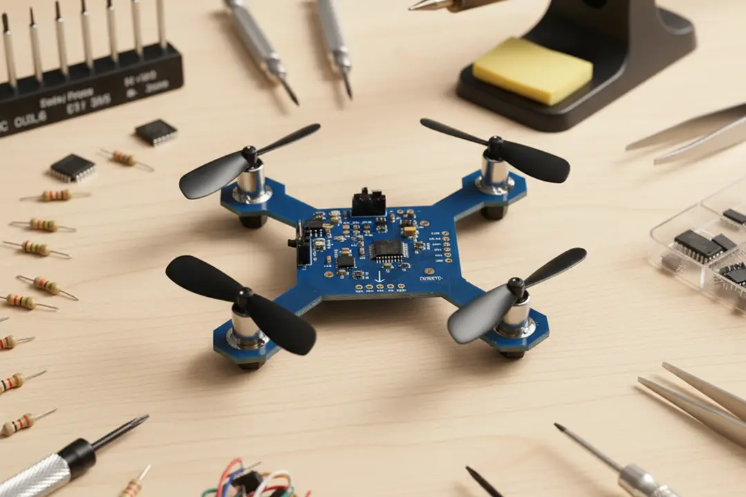
A drone PCB board is a custom-design circuit board. It hosts all the electronic components requires for flight. This includes micro controllers, ESCs, IMUs, GPS modules, power regulators, and more—essentially every pcs of circuitry needed to make the drone fly, navigate, and communicate.
Functions of the PCB for a Drone
- Central Control: Work as the command center, and send instructions from the flight controller to ESCs, gimbal, sensor modules.
- Signal Routing: Data can be distributed among different components inside the drone, such as the IMU, GPS, camera interface, and telemetry radio..
- Power Distribution: Includeed a power distribution board (PDB) to efficiently distribute current from the battery to flight electronics and payload systems.
- Safety: It also protect sensitive electronics, power surges, EMI, vibration, and thermal stress.
Why PCB Design and Manufacturing Matters
If Poorly designed or low-quality PCBs can cause noise, overheating, and even mid-air malfunctions, reducing the reliability of drones. Therefore, ensuring the reliability and performance of the PCB is crucial for handling drone flight control and seamlessly integrating all power and signal requirements onto a single circuit board.
Types of Drone PCB Board and Circuit Used in Drone
There are several important types of drone PCB and circuits used in drones:
| Type of Drone PCB | Primary Function | Where Used in Drone |
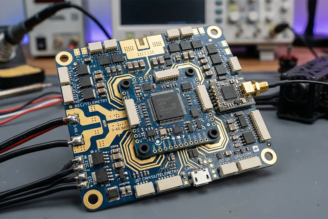
| Flight Controller PCB | The main control board; runs flight algorithms, stabilizes the drone | Center of drone, core to UAV operation |
| Power Distribution Board (PDB) | Shares battery power with all electronic components | Connects battery, ESCs, FC |
| Sensor PCB | Integrates IMUs, GPS, cameras, and more | Navigation, obstacle avoidance |
| High-Speed PCB | Handles real-time video, image transmission, and fast data signals | Live FPV, telemetry |
| Hybrid PCB | Combines rigid and flex materials for space-saving or folding designs | Folding drones, gimbals, compact UAVs |
| Application-Specific PCB | Tailored for delivery, racing, mapping, or unique mission needs | Custom UAV and verticals |
Best Practices:
- For quick-speed flight or realvideo, we can select a dedicated high-speed PCB with controlled-impedance lines for signal fidelity.
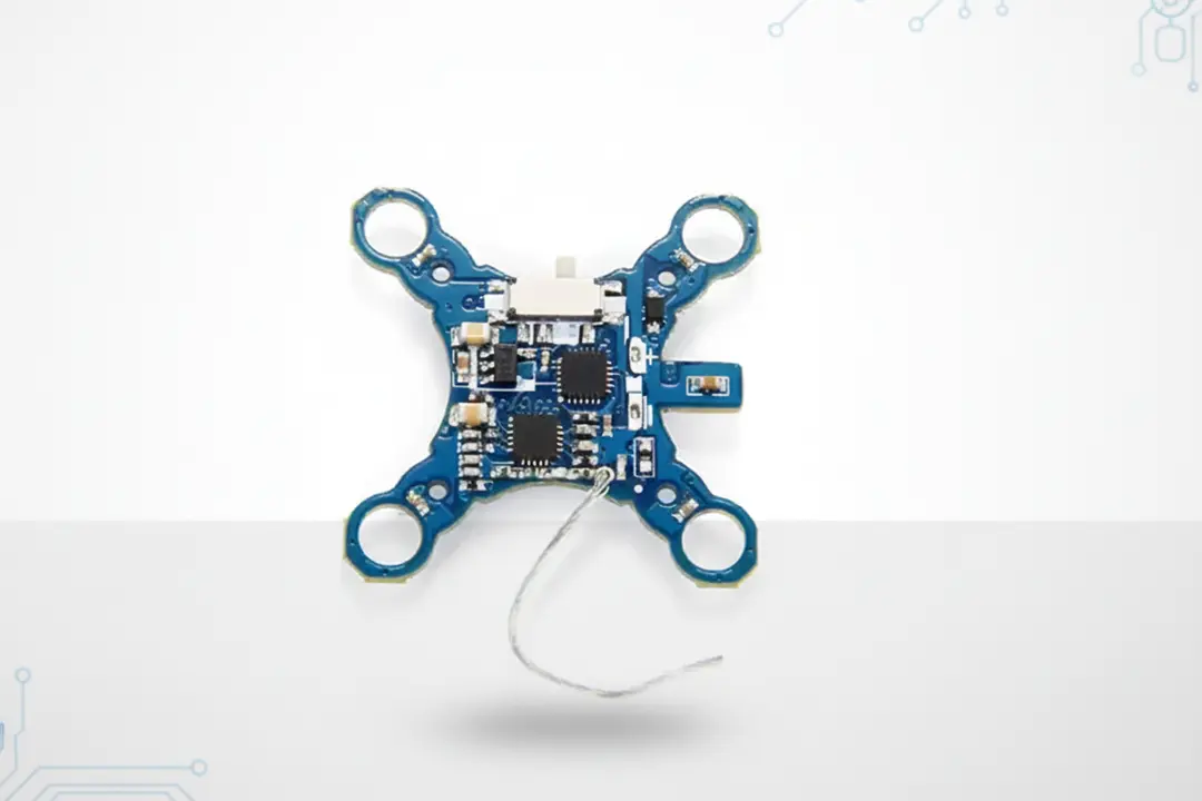
- For mini or folding drones, we can use a rigid-flex or hybrid PCB to reduce loose wires and improve robustness.
Drone PCB Components, Circuit, and Controller
The components of drone PCB boards show the complexity and precision inside the drone. Here are the key different components and their roles:
Essential PCB Components Used in Drone PCBs
- Microcontroller/Processor (Brain of the Drone): Govern all processs, communication with electronic components and flight algorithms.
- Flight Controller: Manager attitude, GPS coordination, PID tuning, and sensor fusion.
- ESCs (Electronic Speed Controllers): It will provide precise motor control via PWM signals.
- Power and Battery Management: It Included voltage regulators, current sensors, MOSFETs, and BMS for safe power distribution.
- IMU (Inertial Measurement Unit): It can Comprise of gyroscope and accelerometer for stabilization.
- Telemetry and Communication Modules: The Relay real-time data to the ground station.
- Camera Interfaces & Gimbal Controllers: It can Enable FPV flight, mapping, or aerial photography missions.
- GPS Module: Its Necessary to autonomous navigation, return-to-home, also
- Connectors, Sensors, and Peripheral Ports: Expansion and flexibility.
Schematic Diagram Example
The drone circuit diagram include a reliable power distribution system, a central processing unit, and sensor fusion. We can save this circuit diagram as a blueprint, ensurs that components such as the IMU and GPS are kept away from noisy power sources to ensure the signal quality.
Materials Used in Drone PCBs
Materials used in drone PCB boards affect weight, durability, and performance. Popular choices include:
| Material | Where Used in Drone PCB | Benefits |
| FR-4 | All-purpose, most drones | Balance of cost, strength, and reliability |
| Polyimide (PI) | Flexible or rigid-flex PCBs | Heat resistance, folding/flexibility |
| Aluminum Core | High-power/heat, racing or heavy-lift drones | Superior heat spreading, rigidity |
| Copper Core | Power-intensive drones | Lower resistance, heavy current flows |
| Carbon Fiber | Racing, light-weight drones | Ultra-light, high strength |
| High Frequency/Rogers | Communication, RF front-ends | Low signal loss, high-speed data paths |
PCB Design Guidelines and Choosing the Right Drone PCB
To design a PCB for a drone need careful planns, simulation, and testing. Need to follow these PCB design guidelines and considerations:
Design Guidelines
- Schematic Diagram: We can start with a organized schematic. It show all control boards, power buses, and peripheral connections.
- Component Placement: Keep noisy components (motors, switching regulators) on separate zones; group related components to keet critical paths short.
- Trace Routing: We use wide traces for power delivery; mini via count on high-speed and high-current paths.
- Layer Stackup: Thge Multilayer PCBs (4–8 layers) are standard for the drone designs, with ground&power for EMI reduction and signal shielding.
- Thermal Management: In order to place a heat-sensitive components on voltage regulators; to provide copper pours, thermal pads, and vias for heat spread.
- EMI Shielding: Ground pours, shielding cans, and carefully trace separad.
How to Choose the Right PCB for Drone
- Application: Is your drone for racing, tooking photo, mapping, deliver, or agriculture? Each use case determines which electronic components and circuits take priority. Such as, race drones depend on the lightweight, heat-resistant PCBs, when mapping drones require PCBs designe for long-distnce telemetry and multiple sensor input.
- Space & Weight Constraints: Weight optimization is very important. Choosing challenged multi-layere circuit boards can reduces wiring while still meeting all flight control and power requirements. Hybrid and rigid-flex PCBs help maximize space utilization and reduce weight, and can also be used in foldable drones or space-compact devices.s.
- Power Components: Choose PCB materials and layouts capable of handling high currents—use thick copper layers and thermal vias for heat dissipation. When design the power distribution board, use thick traces to ensure safety and reliability..
- Thermal Management Needs: If your drone can do in hot climates or with high-current motors, aluminum or copper core PCBs paired with proper thermal management strategies,it can preventing overheating and failure.
- Component Integration: The PCB design and manufacturing practices will let you integrate flight controller, sensor, and PDB functions on the board. This mini the signal loss,can improve reliability, simplifies assembly.
- FAA/CE/EMC Compliance: Commercial drones must regulations on EMI, reliability, and safety.To ensure PCB boards meet IPC standard and undergo thorough testing for vibration, moisture, and electrical safety.
Drone PCB Design Software and PCB Manufacturing
Designing a PCB for drone applications has never been easier, thanks to advanced PCB design software and the global PCB manufacturing industry.
Best PCB Design Software for Drone PCB Board
- KiCAD (free, open-source, deep community support)
- EAGLE (field like for schematic diagram and board layout)
- Altium Designer (professional, use in commercial drone PCB design)
- Fusion 360 Electronics (better integration with mechanical design for UAVs)
How to use PCB design software:
- To builtthe schematic diagram with all drone PCB components—flight controller, ESC, BMS, sensors, and connectors.
- Define design rules: the trace widths, viaholes, controlled impedance for RF/video, and keep areas.
- Simulate for EMI, signal integrity, and heat dissipation.
- FetGerber files and Bill of Materials (BOM) to send to PCB factory.
PCB Manufacturing for Drones
- ChooseaPCB manufacturers with rich experience in applications.
- Standard drone PCB boardare FR-4, but specify hybrid, flex, or metal core when needed.
- Ask thesurface finishes for performance and durability.
- For production, use automated machine(SMT pick-and-place ) to improve quality.
- Request functional and environmental testing (thermal cycling, vibration, moisture) as part of quality control.
Quality Control Checklist:
| Step | Check For |
| Visual Inspection | Solder defects, alignment issues |
| Electrical Testing | Shorts/opens, correct supply lines |
| Functional Testing | Microcontroller, ESC, sensors |
| Environmental Testing | Vibration, temperature, humidity |
Thermal Management and Reliability in Flight Control PCB

In order to ensure thermal management of the flight control PCB, it is important to note that drones generate heat during flight due to rapid changes in power components and motors, as well as environmental factors.
Thermal Management Techniques
- Copper Pours: Use large copper areas under power FETs and regulators.
- Thermal Vias: Conduc heat to interna and bottom layer, increasing cool.
- Heatsinks: Apply to ESCs and areas with high current/voltag componen.
- Careful Component put: Separate heat-sensitive analog ICs from hot power components.
- Aluminum or Copper Core: Use a extreme case—delivers the best drone PCB board reliability for industrial/military/UAM drones.
Reliability & Performance Tips
- Let the board spard withconformal coating to prevent corrosion and moisture ingress.
- Use mechanical standoffs andabsorbing grommets for vibration resistance.
- Follow IPC design guidelines for pad sizes, trace widt, and clearances based on v&c
- Integrate redundancy for flight critical paths; such as, backup IMU or dual battery inputs.
Ensuring the Best Drone PCB Board Performance
How to ensure the drone PCB meet the needs of drone missions and delivers the best reliability and performance?
- Board Testing: Test every PCB after assmbly for function, EMI, and high-frequency integrity.
- Documentation: Save the schematic diagram, PCB layout, and bom for each
- Assembly: Use quality connectors and avoid stacking components on side, which may cause warping.
- Component Matching: Match motor/ESC capability to supply and PCB trace ratings—never undersize for current.
- Modularity: Consider modular PCB when develope fleets, allowing fast replacement of faulty flight controllers or power boards.
- Firmware Upgrades: Include headers for USB/UART so the flight controller PCB can be easily update and debugge.
- Field Logging: Incorporate data logging for real-time PCB and drone circuit board monitoring during operation.
Step-by-Step: How to Make the Best Drone Using High-Quality PCB
This guide to drone PCB manufacturing enables you to make the drone of your dreams:
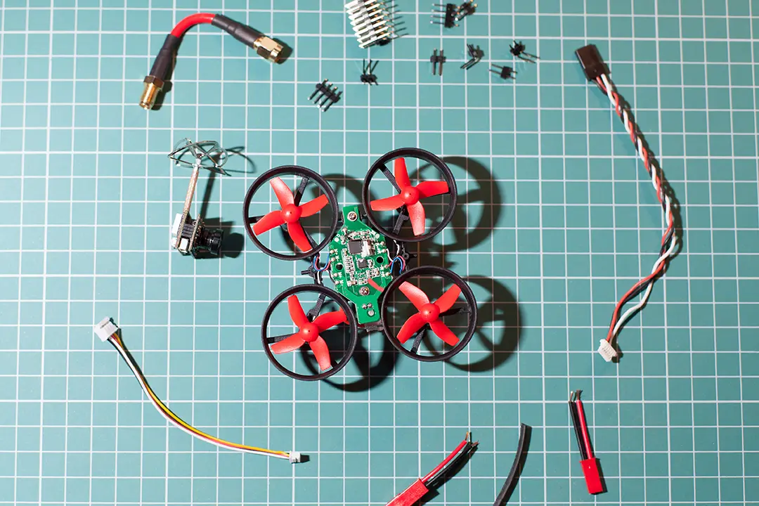
1. Define Mission Requirements
- Consider size, flight time, payload, sensors, and communications.
2. Schematic Diagram Planning
- Layout the major components: flight controller, ESC, PDB, IMU, telemetry, and sensors.
- Group components for shortest signal/power paths.
3. PCB Design
- Use PCB design software for schematic capture and layout.
- Run DRC (Design Rules Check) for electrical and mechanical compliance.
- Simulate thermal and EMI performance.
4. PCB Board Prototype
- Send Gerber files to a quality PCB manufacturing house.
- Assemble a prototype using SMT/SMD services.
5. Assembly and Initial Test
- Mount components like sensors, flight controller, and power circuits.
- Test with dummy loads before installing in the drone.
6. Mount on Drone, Final Test, and Tuning
- assemblethe PCB in the frame with stencil.
- Do full checks: receiver binding, ESC programming, IMU calibration.
- Tune PID and flight parameters in field.
7. Data Logging, Feedback, Improvement
- Log all PCB signal during test; review for component heating, signal integrity, or communication loss.
- Improve the PCB design based on findings, iterate for the next revision.
Conclusion: Creating the Best PCB Board for Drone Needs
A well-executed PCB for drone projects is the foundation of any high-performing UAV. By following the tips in this guide to drone PCB board design and manufacturing, understanding the PCB components used in drone PCBs, prioritizing reliability, and using the right materials, you lay the groundwork for mission success.
Summary Table: Key Points for the Ultimate Guide to Drone PCB
| Step | Key Consideration |
| Select the Right Type | Match application (flight control, sensors, PDB, hybrid) |
| Material Selection | Align with size, weight, and thermal needs |
| Schematic & Layout | Organize circuit, keep traces short, group components close |
| PCB Design Software | Use advanced software to simulate and check design |
| Power & Signal Quality | Ensure heavy-duty traces for power, impedance-matched tracks for high-speed signals |
| Thermal Management | Plan for heat—thermal vias, copper pours, heatsinks, placement |
| Testing & QA | Visual, electrical, and environmental tests before assembly |
| Modular Design | Allow for upgrades, field repairs, plug-and-play expansion |
| Documentation | Save the diagram, keep layout and BOM up to date |
| Compliance | Adhere to IPC, FAA, CE standards for the best drone performance |