Introduction to Printed Circuit Board (PCB) Component
Virtually every electronic device you use—whether a smartphone, computer, television, or piece of industrial machinery—relies at printed circuit board (PCB) packed with count less electronic component. The art and science of circuit board component identification is foundational for anyone work in electronic, from designers and technicians to engineers and hobbyist.
Understanding circuit board component and how to identify components on a pcb is essential for:
- Effective troubleshoot and repair.
- Reliable pcb assembly.
- Efficient maintenance.
- And innovation in electronic design.
This deep-dive guide will help you learn how to identify the component type on any circuit board—give you the confidence to tackle everything from basic repair and modification to advanced diagnostics and PCB manufacturing.
Understanding Circuit Board Components
PCB serve as the backbone of electronic device, provide both a mechanical platform and an electrical circuit that host and interconnect all the component needed for various circuit functions. The circuit board parts themselves directly affect circuit board design, functionality, and performance.
What is a PCB?
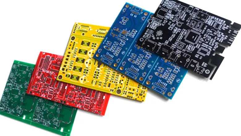
A PCB (printed circuit board) is a flat board, typical made from an insulating material such as FR-4 fiberglass, with copper trace and pad etched or printed onto its surface. It serves as both the wiring and the mounting platform for component on a pcb.
Why is Component Identification Important?

- Ensures accurate identification for component replacement and correct function of the PCB.
- Prevents cost mistakes when testing or repairing PCBs.
- Supports effective pcb assembly and quality control during PCB manufacture.
- Aids in understanding how different component—both active and passive—interact within the circuit.
Key Features of PCB Parts
- Component include everything from small surface-mount components like resistor and capacitor, to larger electromechanical components like relays and connectors.
- Each pcb component has a specific symbol and reference designator, aiding both assembly and future troubleshooting.
- Many printed circuit board will have a part number printed, barcodes, or QR codes for advanced traceability.
PCB Parts and Their Functions
PCB part can be broken down by their function and their role within the electronic circuit. Here’s a quick overview:
| Component | Reference | Function in Circuit Board | Common Usage |
| Resistor | R | Limit current, set voltage in a circuit | Signal conditioning, pull-ups |
| Capacitor | C | Store energy, filter noise, smooth voltage | Power rails, coupling |
| Inductor | L | Store energy in a magnetic field, filter signals | RF, power supply |
| Diode | D, ZD | Allow current flow in one direction, protection | Rectification, voltage reg. |
| Transistor | Q | Switch or amplify signals | Logic, power control |
| Integrated Circuit | IC, U | Logic functions, signal processing | Controllers, op-amps |
| Switch | S | User input, control circuits | Reset, power, mode controls |
| Relay | K | Isolate and switch high-power circuits | Power supply, automation |
| Fuse | F | Protect other components from overcurrent | Input protection |
| Connector | J, P, CON | Establish electrical connections with other devices | Power, data, signals |
| Crystal/Oscillator | Y, XTAL | Timing/reference signals | Clocks, communication |
| Potentiometer | VR, POT | Adjustable resistance for calibration | Volume, tuning, biasing |
| Test Point | TP | Allow easy measurement within circuit | Debugging and servicing |
Components on a Circuit Board: Classification & Characteristics
A comprehensive overview of component on a circuit board means know whether they are active, passive, or electromechanical—each with unique identifiers and functional roles.
Categories of PCB Components
- Passive components like resistors and capacitors cannot introduce energy, but shape current flow and voltage.
- Active component (transistors, ICs, diodes) control circuit direction, switch electronic signals, or amplify signals.
- Electromechanical components include relays, switches, connectors, and batteries; they interact with the environment or user.
PCB Manufacturing and Circuit Board Design for Component Identification
How Circuit Board Design Influences Identification
Good circuit board design enhances traceability and simplify maintenance. Here’s how:
- Clear Silkscreen Marking: Reference designators (like R1, C3, D7) are printed onto the pcb surface for easy location and identification, assist in both pcb assembly and subsequent troubleshooting.
- Logical Component Placement: Group related part (e.g., all power supply component together) makes it easier to found and test pcb parts.
- Physical Board Feature: Slot, cutout, and mount points guide where connectors and large components like transformers go, preventing assembly errors.
- Test Points: Integrated specifically for troubleshoot and test during PCB manufacturing.
Modern Trends
Many printed circuit boards now use barcode and QR codes to catalog every components and assembly operation, supporting advanced component traceability—an essential part of modern electronic quality control.
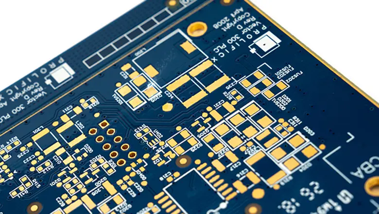
PCB Surface Terminology
- Pads/Pins: Where individual component make contact with trace.
- Traces: The copper “wires” that make up the circuit.
- Vias: Plated holes connecting different copper layer.
- Planes: Large areas dedicated to ground or power, enhancing EMI reduction.
Identifying PCB Components: Step-by-Step Guide
Accurate identification of components on a pcb requires both sharp observation and a system process.
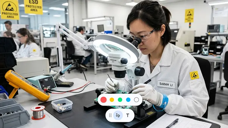
1. Visual Inspection
Start by examine the pcb surface with good lighting and if possible, a magnifier or microscope. Take note of:
- Component shapes: Rectangular component often indicate resistor or capacitor, while rounder ones maybe inductor or through-hole electrolytic capacitor.
- Marking: Color bands on resistors, alphanumeric coding on SMT resistors and capacitors, or part number printed on ICs.
- Silkscreen Reference: R, C, Q, IC, D, VR, etc.
- Pin and orientation: Polarity mark (e.g., banded side of a diode, notch on IC).
- Damage: Burn mark, bulging capacitor, cracking
2. Cross-Reference with Schematics
- Find the schematic: If available, match the designators and values to their circuit functioning.
- If not available, use data-sheet and online resources—most major electronic components have their info readily accessible.
3. Testing Components
- Use a mult-imeter to check resistors (measures in Ohms), continuity on diode, voltage at test point, and capacitance on capacitor.
- For more advance work, an LCR meter measure inductance and complex impedance, while an oscilloscope visualize circuit functions.
Component Identification Techniques: Visual and Analytical
Identifying pcb component often starts visually and proceed analytically. Mostly components on a circuit board are marked with one or more of the following:
- Component Designators: Letters and numbers silkscreen onto the pcb surface (e.g., R12, C103, D5, Q4) accord to convention.
- Physical Shape: Rectangular components near small signal paths are like resistors or capacitor; three-legged packages often mean transistors; eight or more legged ICs often provide logic functions or control tasks.
- Marking: Many electronic component have code, value marking, or a full part number printed atop. For SMT parts, these can be short and cryptic, require lookup in SMD codebooks.
Analytical Techniques
- Part Number Cross-Reference: Key for ICs, transistor, and diodes. Looking up the part number printed on the component in datasheet catalogs.
- Color Code/Alphanumeric Values: Used for resistor and some capacitors. For example, a resistor with bands brown-black-orange-gold is 10,000Ω (10kΩ) with+/- 5% tolerance.
- Pin Count and Package Style: Helps differentiate between logic ICs, microcontroller, operational amplifier, and other complex pcb components.
- Function Testing: With a multimeter, LCR meter, or components tester, you can check whether a component act as expected within the circuit.
- Circuit Location: Component near connector are use to establish electrical connections or power regulation; parts near chip often assist with signal filtering or timing.
Detailed Guide to Common Components Found on Circuit Boards

Let’s explore the roles, identification trick, and example application of the most commonly circuit board parts.
Resistors
- Purpose: Limit current in a circuit, divide voltages, form timing network, and pull-up/down in logic circuit.
- Identification: Through-hole type show color band; surface-mount resistor have alphanumeric value (“103” = 10kΩ).
- PCB Context: Locate everywhere from signal line to power rail. In power sections, expect higher-wattage rectangular component.
- Typical Use: Set gain in amplifiers, current limiting for LEDs, voltage dividers in analog input circuitry.
Capacitors
- Purpose: Storing electrical charge, block DC, smooth power supply signals, filter high-frequency noise.
- Identification: Mark with uF or pF rating, code numbers, or case shape (cylindrical for electrolytics, rectangular for ceramics).
- PCB Context: Found near ICs for decouple, at power inputs for filtering, and in timing circuits.
- Extra Detail: Polarized electrolytic are used for power rails; non-polarized ceramics for high-frequency filtering.
Inductors
- Purpose: Store energy in a magnetic field, filter AC signal, suppress EMI, set oscillator frequency.
- Identification: Labeled “L” with numeric codes; often larger and more robust than resistors or capacitor.
- PCB Context: Prominent in power supplies (as choke) and radio frequency circuits.
- Example Use: EMI filters at input, smoothing in switch-mode power supplies.
Diodes
- Purpose: Allow current flow in only one direction, protect other component, rectify AC, providing voltage references.
- Types: Standard, Zener, Schottky, and light-emitting diode (LEDs).
- Identification: “D” or “ZD” for Zener diodes, band marking for the cathode end.
- PCB Usage: Rectification in power, protection near connector, signal indication (LEDs), voltage regulation (Zeners).
Transistors
- Purpose: Switch, amplifys, or regulate signals.
- Identification: “Q” plus package shape; three or more pins/leads. Part numbers identify type and function.
- On PCB: Used in logic switch, amplifiers, voltage regulators, and as part of power control systems.
- Example: SOT-23 package near an MCU might be a MOSFET load switch.
Integrated Circuits (ICs)
- Purpose: Perform logic functions, microprocessing, voltage regulation, and memory task.
- Identification: “U” or “IC” plus a part number print on a rectangle or square package, varying in size.
- On PCB: Central to almost all modern electronic device. Finding at the heart of computing, control, and interface circuitry.
Switches
- Purpose: Manually change circuit state (on/off, mode selection, reset).
- Identification: “S” with descriptive nearby text.
- Common on: User interfaces, power paths, system reset lines.
Relays
- Purpose: Use low-power control signals to switch high-power circuit; providing
- Marking: “K” or “RY” in schematics.
- PCB Use: Used for power management, safety-cutoff, or when switch high voltages/currents.
Connectors
- Purpose: Used to establish electrical connections from the pcb to the outside world or between boards.
- Identification: “J”, “CON”, or “P”.
- Varieties: Pin header, socket, terminal block, edge connector.
Advanced Tips for PCB Parts Identification
- Use Barcode and QR Code Scanners: Modern circuit board include barcode for rapid identification of component and traceability back to manufacture batch and supplier.
- Photographic Databases: Compare unknown pcb parts or surface-mount component with large online databases, particularly for older or obscure parts.
- Component Testers: Useful for quick identifying value and polarity on unmarked resistors, diodes, or transistors.
- Heat and Fault Finding: Thermal camera can help find overheating or failed component in complex assemblies even when all markings are unreadable.
Importance of Accurate Identification in PCB Assembly and Repair

Accurately identifying components on a pcb is a critical part of pcb assembly and circuit board repair:
- Reduces PCB Assembly Errors: Ensure all component perform their intend circuit functions and reduces costly production line rework.
- Secures Device Reliability: Prevent substitution error that may only present as fault after shipment or extend operation.
- Improves Troubleshooting Efficiency: Identifies failure-prone parts like electrolytic capacitors, SMD fuses, or power control IC quick.
- Supports Documentation: Modern electronic traceability (serial numbers, lot codes, barcode) hinges on accurate records of the electronic component fitted, its supplier, and even its performance history in deployment.
Case Study: A telecommunications board was plag with random failures in the field. Traceability records and barcode history revealed a supplier change in the batch of SMD capacitors, which were later found to be counterfeit. Because pcb part numbers and barcodes had been properly logged, the faulty batch was quick isolate and replacements issued.
Component Documentation and Traceability
Document every electronic part during manufacturing and repair with:
- Reference Designator: R13, C245, D11, IC4.
- Part Number: Manufacturer official code, e.g., LM393P, SN74LS00N.
- Unit Function: g., “5V regulator,” “8-bit logic buffer,” “main battery connector.”
- Supplier and Batch: Essential for quality control, recall, and warranty work.
Frequently Asked Questions: Identifying Components on a PCB
Q: How do I identify the component that failed on my PCB?
A: Start with a visual scan; look for crack, burned, bulging, or discolored component. Use a multimeter to check basic function (for open/short or expected resistance/capacitance). Cross-reference designators and marking with the schematic and BOM.
Q: What are some examples of components in a circuit that often need repair?
A: Power supply-relate component—like surface-mount fuses, large electrolytic capacitors, Schottky diodes, and power transistor—are often first to fail due to their thermal and electrical stress.
Q: Can I substitute different components if I can’t find an exact match?
A: Only if the replacement matches all electrical rat and physical fit, and ideally after confirming with the schematic or data-sheet that it won’t impact entire board function.
Q: How does PCB layout affect troubleshooting?
A: Clear pcb layout with well-marking component designators, separated domains (like analog, digital, and power control areas), and dedicated test points simplifies circuit board component identification. It help technicians follow signal path, understand the role of individual component, and quickly locate fault in the electrical circuit.
Q: What are the risks of misidentifying a printed circuit board component?
A: Misidentification can result in further circuit damage, functional failures of the entire board, increase repair cost, and potential safety hazards—especially for components found in power supply or current regulation roles. Always verify electronic component values and ratings before replacement or modification.
Q: How should I approach identifying components on a vintage or unmarked PCB?
A: Begin by drawing a partial schematic from visible traces, noting common arrangement patterns. Use component tester tools for unknown passive components like resistors and capacitors. Research similar pcb boards or devices online, as many printed circuit boards share circuit design practices and component choices within the same family or era.
Q: Are there standard lists for components found on circuit boards?
A: Yes—a typical components list includes resistors, capacitors, diodes, transistors, inductors, integrated circuits, connectors, relays, fuses, oscillators, and switches. Familiarity with this list is crucial for both pcb manufacturing and repair.
Q: What extra steps do PCB manufacturers take for difficult component identification?
A: During pcb manufacturing, designers increasingly use barcodes or QR codes, full reference designators on both sides of the pcb, and digital documentation in traceability software. These methods greatly assist in identifying pcb components when physical markings are missing or damaged.
Conclusion: The Role of Component Identification in Modern Electronics
Circuit board component identification is a cornerstone skill in electronic—one that connects theory, design, assembly, troubleshooting, and repair. Proper identification of pcb components ensures device performance, safe, and ease of maintenance across every electronic device, from consumer gadgets to life-critical industrial controls.
Understanding circuit board component is essential not only for designers and repair professionals, but for anyone curious about how pcb work, how circuit boards include so many distinct yet interconnected electronic part, and how faulty electrical components may affect the entire board.
From reading resistor color codes and part number printed on ICs, to identifying surface-mount components or electromechanical components like relays and connectors are used for power control, accurate identification methods support robust repairs and smarter circuit design.