Introduction: What is Mixed Technology PCB Assembly?

The electronic manufacturing industry is developing at a very rapid pace. Mixed-technology PCB assembly is an assembly method that transforms traditional approaches. The essence of this method is the mounting of various electronic components onto the surface of a printed circuit board. During this process, design engineers and PCB manufacturers must work together to accomplish multiple objectives. They must ensure stable product performance and reliable quality, while also preventing increases in product size, cost or design rigidity.
Mixed-technology PCB assembly is a specialized method of circuit board manufacturing. This method employs two techniques simultaneously on the same circuit board. The first is surface mount technology, which involves mounting components directly onto the board’s surface and enables product miniaturization. The second is through-hole technology, which involves inserting component leads through holes in the board for fixation, providing high stability and mechanical strength for components such as connectors and large capacitors. The combination of these two techniques is primarily used in products that require both compact size and structural robustness. Mixed-technology PCB assembly makes design more flexible and can adapt to the diverse needs of the modern electronics manufacturing industry. This approach helps achieve products with high performance, high cost-effectiveness and high reliability.
Fundamental Technologies: SMT, THT and Mixed Assembly
Understanding the advantages of hybrid assembly requires a prerequisite. This prerequisite is clarifying how three technical forms define mixed process PCB. The first technical form is surface mount technology, which functions to achieve component miniaturization. The second technical form is through-hole technology, which functions to provide high mechanical strength for components. The third technical form is the combination of the previous two, which functions to balance miniaturization and high strength on the same circuit board. These three forms together constitute the foundational definition of mixed process PCB.
Surface Mount Technology (SMT) in PCB Assemblies
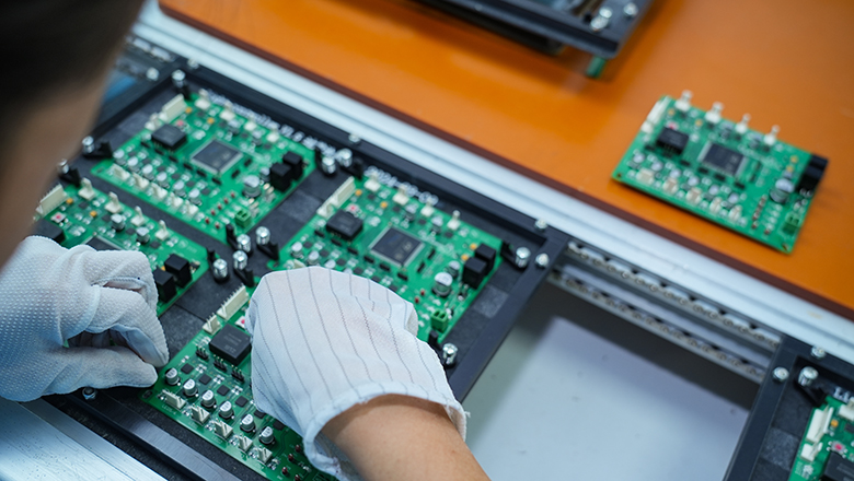
SMT (Surface Mount Technology) enables direct mounting of components on the surface of the PCB. SMT assembly is common for compact, automated, high-speed PCB manufacturing and assembly—perfect for the miniaturized circuits found in smartphones, wearables and high-density computing.
Key SMT Attributes:
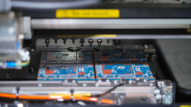
- Automated placement of SMT components via pick-and-place machines.
- SMT components are soldered onto pre-printed solder paste pads.
- Allows high-density layouts, reducing PCB size.
- Increases throughput, reduces assembly costs.
Through-Hole Technology (THT) in Circuit Board Assembly
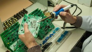
THT assembly involves inserting leads of larger or more robust components through pre-drilled holes in the PCB. Through-hole parts are then soldered from the opposite side of the board.
THT is vital for:
- Components requiring high mechanical strength (connectors, transformers).
- Handling higher currents or supporting power electronics.
- Applications needing easier rework or field repair.
Mixed Technology PCB Assembly: Combining SMT and THT
Mixed technology PCB assembly refers to a circuit board manufacturing approach. This approach results in a printed circuit board that contains both Surface Mount Technology (SMT) components and Through-Hole Technology (THT) components. This mixed assembly process utilizes SMT to achieve compact, automated placement of components. This process relies on THT to ensure the mechanical stability of component connections. Mixed technology provides electronics manufacturers with a circuit board assembly solution. This solution enables the circuit board assembly to achieve optimal space utilization, performance and reliability simultaneously.
What makes mixed technology unique?
- Combines surface mount technology (SMT) and through-hole assembly.
- Maximizes assembly solutions flexibility.
- Supports a broader range of applications of mixed technology.
- Reduces assembly and manufacturing bottlenecks compared to pure THT.
Key Benefits of Mixed Technology PCB Assembly

Let’s break down the benefits of mixed technology PCB assembly and why so many industries rely on this approach.
Mixed Assembly Advantages
Greater Design Flexibility and Supports Innovative Layouts
- Designers can place high-speed, compact SMT components in high-density areas of the circuit board. Designers simultaneously retain sensitive or high-power THT components in another area of this same circuit board. The design approach described above achieves an optimized circuit routing scheme. This design method ultimately leads to an enhancement in the overall functionality of the circuit.
Mechanical Strength & Reliability
- THT connectors and large capacitors are capable of withstanding mechanical stress, resisting vibration interference, and enduring repeated insertion and extraction cycles. This tolerance capability is a critical performance indicator for printed circuit boards used in automotive electronics, aerospace equipment and industrial control applications.
Enhanced Thermal Performance
- Through-hole components excel at dissipating heat; placing THT parts away from sensitive SMT parts prevents thermal overlap with nearby SMT and guards against overheating.
Cost Optimization
- SMT process is mainly applied to the automated mounting of mass-produced components, which can shorten the PCB assembly cycle and lower manufacturing costs. THT process is selectively used in specific scenarios for high-value components that perform critical tasks, and this selective application strategy helps companies avoid unnecessary capital investment.
Legacy Component and Modern Integration
- Mixed assemblies allow continued use of legacy through-hole components alongside new SMT and THT technologies, making product refresh and upgrades seamless.
Streamlined Prototyping to Full Production
- Mix of manual placement for prototypes and automated assembly for production reduces time to market and supports design changes without major cost penalties.
Applications of Mixed Technology PCB Assemblies
Applications of mixed technology PCB assembly span nearly every sector that values durability, compactness and performance.
Key Industries Using Mixed PCB Assembly:
Industrial Electronics: Control panels, PLCs, motor drivers; combine SMT ICs with THT connectors/relays.
Automotive Electronics: ECUs, power modules, sensor interfaces; benefit from robust connector durability and dense analog/digital processing.
Medical Devices: Portable imaging equipment, lab instruments, patient monitors; rugged inputs (THT) with miniaturized processing (SMT).
Aerospace and Military Electronics: Avionics, radar cards, communications; reliability and certification demands require mixed-technology PCB assembly.
Power Electronics and Energy: Mixes high-power, through-hole assembly for chassis-mounted parts with automated placement of SMT controllers.
Why Mixed Assemblies Excel
- Applications include situations with overlapping requirements of mechanical strength, reworkability and space efficiency.
- Where thermal management is a concern, THT offers heat dissipation, while SMT maximizes circuit density.
- Mixing these methods allows for optimized manufacturing and assembly—without compromising reliability.
The Mixed Assembly Process: Combining SMT and THT
The assembly process for mixed-technology PCB assembly is more nuanced than using SMT or THT alone. Here’s a step-by-step walkthrough of how top PCB assembly services handle mixed technology PCB assemblies:
Mixed Assembly Workflow Overview
| Step | SMT Components | THT Components | Key Considerations |
| Board Preparation | Solder paste stencil printing | Hole drilling | DFM checks, panelization |
| Automated/Manual Placement | Automated pick-and-place | Manual or robotic insertion | Assembly solutions tailored to both |
| Soldering | Reflow oven | Wave/selective/manual soldering | Overlap with nearby SMT parts considered |
| Inspection | AOI, x-ray, SPI | AOI, x-ray, manual | Away from sensitive SMT parts |
| Cleaning | Optional | Always after wave solder | Removing residues for reliability |
| Testing | ICT, functional test | ICT, functional test | Ensures finished PCB meets all specs |
Detailed Assembly Method Steps
- SMT Assembly:Solder paste applied to the surface of the PCB, then automated placement of SMT parts. SMT and through-hole regions are sequenced to reduce thermal risk and optimize throughput.
- THT Assembly:After SMT reflow, THT components and through-hole parts are inserted—manually or semi-automatically. Placement occurs away from zones where SMT solder joints may be compromised.
- Soldering Methods:
- Reflow soldering for SMT.
- Manufacturers use wave soldering to complete the soldering of THT components, a process that is only suitable for the assembly of single-sided printed circuit boards. For circuit boards with densely arranged components or those adopting double-sided assembly, manufacturers will choose selective wave soldering, while operators carry out manual soldering under special circumstances when the heat-affected zones of THT pins overlap with those of adjacent SMT components.
- Automated Optical Inspection (AOI):AOI equipment undertakes the task of detecting misalignment of SMT and THT components. This equipment identifies the presence of defective solder joints. This equipment detects the occurrence of tombstoning. AOI technology prevents high-density layouts from hiding defects. This work avoids creating inspection blind spots caused by overlap with adjacent SMT components.
- Automated X-Ray Inspection (AXI):This inspection method is primarily used in areas with densely packed components. Examples include BGA packages or positions where surface mount components overlap with through-hole components. It is used to identify solder joint defects hidden beneath components that are difficult to observe directly.
Manual Inspection and Functional Testing: Skilled technicians visually inspect key assemblies and conduct in-circuit or system-level functional tests. - ICT (In-Circuit Testing):Verifies the integrity of the circuit, particularly beneficial when design for assembly incorporates accessible test points for both SMT and through-hole assembly.
Environmental & Burn-In Testing: Common in aerospace, military and automotive electronics, burn-in simulates real-world stress, validating the resilience of both SMT and THT on a single board.
This multi-tiered approach ensures mixed technology PCB assemblies meet stringent industry standards and performance criteria—without compromising speed or cost in high-volume PCB manufacturing and assembly.
PCB Design Rules for Mixed Technology

Successful mixed technology PCB assembly is rooted in deliberate, detail-oriented PCB design. Following design rules enables smoother manufacturing and assembly, minimizes errors and bolsters overall electronics reliability.
Essential Design Rules
Component Layout & Sequencing:
- Separate dense SMT zones from THT areas to avoid solder bridging and facilitate automated placement.
- Place THT connectors or large capacitors strategically away from sensitive SMT parts to avoid thermal stress and streamline the assembly process.
Hole Sizing and Pad Design:
- For through-hole components, follow IPC design rules for hole diameter and annular ring sizes. Proper sizing avoids weak joints or costly rework during circuit board assembly.
Thermal Management:
- Add thermal reliefs to THT pads linked to ground planes, preventing cold joints during wave or selective soldering.
- Plan SMT and THT regions so that thermal overlap with nearby SMT is minimized, particularly if multiple soldering cycles are needed.
Testing and Inspection Access:
- Design for test (DFT): place accessible test points for in-circuit and functional testing, especially in mixed assemblies.
Design for Assembly (DFA):
- Collaborate with your PCB assembly services provider to ensure that every step—from paste printing to final inspection—aligns with real-world manufacturing and assembly capabilities.
Panelization:
- Use panel arrays to streamline both SMT assembly (for compact automated placement) and THT manual placement. This reduces handling costs and speeds up both prototyping and full production runs.
Cost, Reliability and Manufacturing Considerations
Understanding the economics and reliability impacts of mixed PCB assembly helps guide design and production strategies.
Cost Drivers & Optimization Strategies
- SMT for Compact, High-Volume Production:Most cost-effective for high-density circuit designs and applications across consumer and industrial electronics.
- THT for Power and Mechanical Anchoring:Niche use in high-current or high-stress environments—using mixed technology keeps costs under control by applying THT only where needed.
- Reducing Assembly Stages:Mixed assemblies reduce assembly times by focusing THT only where value-added, while the majority of board area is reserved for fast, cost-efficient SMT.
- Panelization:Increases throughput and allows greater cost control in both automated SMT assembly and THT manual placement.
Reliability and Quality
Reliability is at the heart of every mixed-technology PCB assembly. Combining SMT and THT technologies enables manufacturers to achieve:
- High vibration, thermal and shock resistance without compromising circuit density or feature set.
- Field-repairability—THT components are easier to replace during maintenance, extending product life.
- Lower defect rates, as selective application of each assembly method avoids overburdening either with inappropriate component types.
Manufacturing and Assembly Improvements
- Automation in SMT and THT:Manufacturing and assembly lines now use robots for THT insertion, further speeding up mass production and reducing manual labor costs.
- Design for Manufacturing & Assembly (DFMA):Concurrent engineering practices help identify bottlenecks in the assembly process and eliminate overlapping or redundant steps.
Choosing a PCB Manufacturer for Mixed Technology
Selecting a reputable pcb manufacturer is crucial for the success of any mixed-technology PCB assembly. Here are steps and considerations:
- Experience with Mixed Assembly Technology: Ensure your partner specializes in both SMT and through-hole assembly, with an established record in delivering mixed technology pcbs for your industry.
- Certification and Standards: Select providers adhering to IPC, ISO 9001 and industry-specific standards, which ensures robust assembly process and reliable pcb assemblies.
- Design Collaboration: Your PCB manufacturer should offer design for assembly consultations, helping to preemptively streamline the assembly process and guarantee compliance with design rules.
- Inspection Capabilities: Confirm that AOI, X-ray and manual inspection are part of their standard pcb assembly services—especially for complex mixed pcb assembly projects.
- Prototyping to Mass Production Transition: Ensure your assembly partner can scale with you from prototype runs to full production runs, minimizing supply chain risks and reducing lead times.
Frequently Asked Questions (FAQs)
Q1: What are the typical applications of mixed technology pcb assembly?
A: Applications of mixed technology range from automotive ECUs, industrial control boards and medical equipment, to aerospace modules—anywhere both reliability and compact layouts are needed.
Q2: How does mixed technology pcb assembly enable greater design flexibility?
A: By combining smt and tht technologies, you can densely populate PCBs with digital logic while strategically placing robust, serviceable connectors or power components using THT—without compromise.
Q3: Does a mixed assembly method cost more than pure SMT or THT?
A: Not necessarily. Mixed assembly reduces assembly and overall manufacturing costs by concentrating each assembly method only where it delivers maximum value, avoiding unnecessary expense.
Q4: Can mixed pcb assembly be used for both prototyping and high-volume runs?
A: Absolutely. It is easily scaled—manual assembly for prototypes and automated placement for high-volume manufacturing and assembly.
Q5: What common design rules should I follow for mixed assemblies?
A: Keep SMT and THT regions well defined, avoid overlap with nearby SMT parts during THT soldering and always design for robust inspection and testability.
Conclusion & Next Steps
In the world of electronics manufacturing, mixed technology pcb assembly is the gold standard for delivering high-reliability, space-efficient and cost-effective electronics. By combining SMT and THT—balancing automated placement and manual assembly—engineers create future-proof pcbs for mission-critical applications across every industry.