Introduction to Breadboards and PCBs
Each electronic device make its life as an idea, a prototype circuit assembled quickly in order to prove a concept before scaling up. In the heart of every prototyping work flow there are two platforms: breadboard—a reusable platform, it enabling the creation of circuits without soldering—and the PCB (Printed Circuit Board), the robust, scalable, and professional solution for all finished products.
Most hobbyists, students, and engineers usually work with both breadboards and PCBs some point. Breadboards are ideal for their flexibility and ease of use, when PCBs provide unmatched stability and repeatability. This article inteoduce the key differences, best practices, common pitfalls, and how to make the all-important transition from breadboard prototypes to PCBs ready for PCB assembly and production.
Why Prototyping Matters in Modern Electronics
Prototyping is very important because it also allow designers to build, fix, and improve electronic circuits without the need for soldering or expensive manufacturing. With a breadboard, even a complex circuit designed can be tested and iterate rapidly. This step can help identify design flaws, missing connections, the need for extra resistors, and component mismatches with committing to professional PCB production.
- Breadboard prototypes or solderless breadboards can help visualize current flows and also allow for current measurement through adding an ammeter anywhere in circuit.
- For many projects, especially for beginners or hobbyists, testing circuit connections on a breadboard usually make it easier to understand the circuit and its functionality before making permanent decisions.
As designs mature, breadboards have limited current carrying capacity and lack the durability needed for real-world dvelopment, it also leading to the need for PCBs.
What is a Breadboard? The Reusable Platform for Easy Prototyping
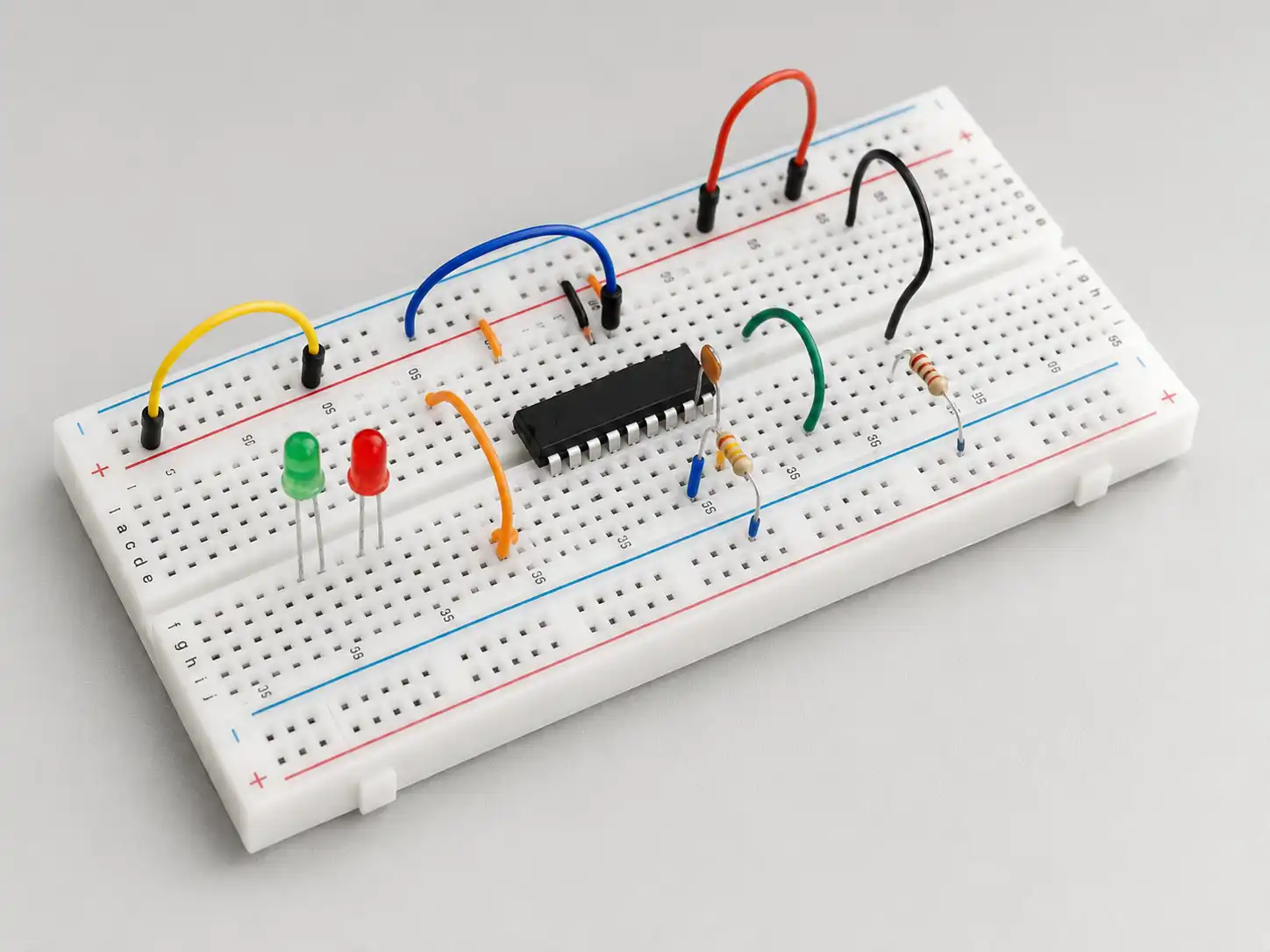
A breadboard is a plastic board, it have a matrix of holes connected by metal spring clips beneath the surface. Components can be placed without soldering—which can making it ideal for short-term projects, education, or experimenting with simpler circuits.
Key Breadboard Features
- Solderless construction: Circuits can be quickly modified.
- Plastic board: Durable for hundreds of uses, though not permanent.
- Power distribution: Common rails make connecting power and ground simple.
- Circuits without the need for soldering: Ideal for low voltage and low current projects.
- Easier to understand the circuit: Layout is visual and accessible.
Use of Breadboards
- Electronic circuits without commitment: For prototyping, temporary repairs, and iterative design.
- Educational tool: Breadboards are incredibly use for students and also for new
- Debugging: Breadboards usually allow us to add an ammeter for current measurement or we can try components like extra resistors before committing to a full circuit board.
PCB Boards Explained: The Foundation of Every Modern Electronic Device
A PCB (Printed Circuit Board) is a professionally manufactured board, it connects electronic components and using etched copper traces. Today’s PCBs range from simple single-layer perforated boards to multi-layer PCBs, we can found in smart phones and advanced electronic boards.
Why PCBs?
- Durability: Open to vibration, movement, and environmental variables.
- Compact design: High-density mount, it can miniaturized the complex circuit architectures.
- Reliability: Under solder mask protection, PCBs can provide strong electrical connections and lasting quality.
- PCB fabrication and assembly: Ideal for commercial-scale production or advanced prototype produced.
Core Elements of a PCB
- Substrate (often fiberglass) for support
- Copper layer(s): The conductive pathways
- Solder mask: Protects copper traces from oxidation and shorts
- Silkscreen: Identifies components and guides PCB assembly
- Vias: Connecting traces and layers in multi-layer PCBs
PCBs are typically designed and using CAD software, it allows the circuit simulation, electrical rules checks, and generating Gerber files—the manufacturing blueprints for PCB fabrication.
Types of PCBs and Their Applications
Main Types of PCBs
- Single-layer PCB: One copper layer; ideal for simple electronic circuits like power supplies or toys.
- Double-layer PCB: Two copper layers; enables more complex routing for products like amplifiers or micro controllers.
- Multi-layer PCB: Three or multi layers; supports compact design, impedance controll, high-speed signals, and advanced EMI shielding.
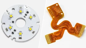
- Flexible and rigid-flex PCBs: Used in wearables and foldable electronics due to their bending capabilities.
- Perforated board (perfboard): Used for semi-permanent prototypes with through-hole soldering (not to be confused with a breadboard).
Applications
- Hobbyist PCB projects (Arduino shields, sensor modules)
- Professional prototypes (IoT, medical, industrial control)
- Consumer electronics (phones, laptops, wearables)
- High-complexity PCB assemblies (telecom, automotive, aerospace)
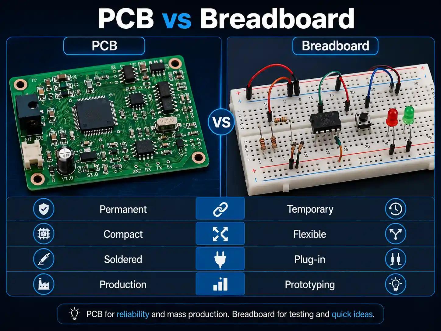
Breadboard vs PCB: Key Differences Between the Two
Table: Key Differences Between Breadboard and PCB
| Feature | Breadboard | PCB (Printed Circuit Board) |
| Assembly | Solderless, reusable platform | Permanent, requires soldering |
| Durability | Short-term, not vibration/heat tolerant | Long-term, robust, environmental |
| Current Carrying Capacity | Low, suitable for simpler circuits | Better current carrying capacity |
| Component Placement | Manual, limited by hole spacing | Any component (SMD, TH, custom) |
| Complexity | Simpler circuits, educational purposes | Complex circuit, multilayer support |
| Scalability | Not possible for mass production | Go straight to PCB for scaling |
| Noise & Signal Integrity | High inductance/capacitance; unshielded | Low noise, high-speed circuits |
| Ease of Testing | Components can be placed & replaced freely | Current measurement on PCBs require you to break tracks or add test points |
| Manufacturing | Instant DIY; no tools needed | Requires PCB manufacturing/fabrication and assembly services |
| Power Distribution | May require bus bars for high current | Traces wider to take more current |
| Customization | Limited to breadboard hole format | Unlimited—any shape, stack, mounting |
Breadboards have limited current carrying ,it can best used for temporary, flexible development of electronic pcbs without soldering. PCBs need professional fabrication, but they also offer better current carrying capacity , which is suitable for all levels of complexity.
Designing a Circuit: Breadboard or a PCB?

When design a circuit, one pivotal decision is to use a breadboard or a PCB.
- Breadboards are ideal when we need to try different ideas, test circuit changes, or conduct educational demonstrations.
- PCBs are typically the durable, high-reliability, scal able products. They need planning, layout skills, and access to manufacturing—but they are essential for modern electronics.
- If you want to build simpler circuits or teaching others about circuits without thedurability, breadboards are very It become easier to understand the circuit due to their visible structure,it also allow us to make circuits without the need for soldering.
- But as you progress to commercial products or need to ensure your current carrying limits, PCBs require thoughtful planning and are essential. If you need better current carrying capacity, less electrical noise, orfit a design into a tight mechanical envelope, it’s time to go straight of the PCB.
Key Considerations When Choosing
- Testing Circuit & Iteration: Breadboards excel is flexible, and allow frequent changes to the whole circuit. PCBs are best choice when our design has stabilized, and you require repeat ability and advanced features.
- Component Access: Breadboards make accessing the pins of integrated circuits simple—great for learning and debugging. However, PCBs are especially needed for surface-mount include complex devices, where access to the pins can be restricted.
- Current Measurement: On breadboards, we can add Current measurement on PCBs require planed for test pads or breakable tracks.
Transitioning from Breadboard Prototypes to PCBs: Step-by-Step Guide
Transitioning from breadboard prototypes to PCBs is a defining moment in each hardware project. Here is how to move from initial concepts to robust, doable products:
1. Refine Your Breadboard Prototype
- Test all scenarios, including fault cases.
- Add extra resistors or swap components as needed for optimization.
- Document your working layout, noting any strange behaviors or special wiring.
2. Prepare Your Schematic
- Use CAD software (e.g., KiCAD, Eagle) to draw the finalized circuit.
- Ensure all components are available as real PCB footprints—SMD or through-hole.
3. PCB Design and Layout
- Place components logically, grouping similar blocks (logic, power, analog).
- Route signals efficiently—keep traces short, make power traces wider to take more current, and avoid tight corners to reduce EMI.
- Plan for future testing: PCBs require you to break tracks or plan for test points if you want measurement access in your assembled board.
4. Design Rule Checks and Gerber Files
- Run electrical and design rule checks: check clearance, the minimum trace width, and the other manufacturer specs.
- Export Gerber files—the universal format suitable for PCB fabrication.
5. PCB Fabrication and Assembly
- To choose a reliable PCB manufacturer is very important. Especially layers, copper weight, solder mask color, and silkscreen.
- Consider working with an EMS (electronics manufacturing services)partner for PCB assembly, and include PCB designs.
6. Assembly, Testing, and Troubleshooting
- Once the pcb arrive, we can start to assemble with the correct parts. Use professional soldering or SMT assembly as needed.
- Test thoroughly, confirming every connection and measurement align with your breadboard prototype.
Case Studies: From Concept to PCB Assembly
Hobbyist Home Automation Project
A hobbyist usually built lighting and climate controls on a breadboard, to enjoy flexibility as he tested relay and sensor combinations. Eventually, he transitioned the design to a custom PCB board, to use CAD for layout and a local shop to PCB manufacture. By making the traces wider where high current was needed, his system is now running reliably for years, something is impossible with the original plastic board.
Startup IoT Device
A tech startup started with breadboard prototypes to quickly iterate their smart sensor’s circuitry. When ready for pilot production, they moved their breadboard prototypes to PCBs. This step was crucial—breadboards had too much noise and loose connections, but the new PCBs provided stability and easy assembly for their demo units at investor meetings and field trials.
Expert Tips for Breadboard and PCB Design
- Documentation: Take photos of your breadboard layout and print wiring diagrams. Breadboards are easy to rewire incorrectly!
- Power Distribution: For higher currents on a breadboard, use multiple parallel wires. On PCB, make power traces wider to avoid overheating.
- Component Sourcing: Check the stock availability and price of all components before designing a
- PCB Layout: To keep analog and digital grounds separately if needed; always provide solid ground and power planes for noise reduction.
- Thermal Management: For power devices, we can add copper pours connected to pads to dissipate heat.
- Testing Points: For easier time debugging, we can plan for test points and use vias for measurement on PCBs.
Frequently Asked Questions (FAQ)
Q: Can circuits be built on breadboards without soldering?
A: Absolutely. Breadboards are solder less platforms, it also allow circuits without the need for soldering, and make them perfect for prototyping and education.
Q: Why do PCBs require a solder mask?
A: The solder mask insulate and protect the copper traces, it will prevent accidental shorts, oxidation during both manual and PCB assembly.
Q: Are breadboards good for complex circuits?
A: Breadboards are best for simpler circuits or initial prototypes. As complexity (or frequency) increases, noise, capacitance, and crosstalk issues appear. Multilayer PCBs is the answer for high-complexity or high-speed boards.
Q: What’s the key difference between a solderless breadboard and a perforated board?
A: Solder less breadboards is easy, tool-free connections, when perf boards need us to solder components for a semi-permanent build, its useful for intermediate-level projects.
Q: Can you go straight to PCB without breadboard prototyping?
A: If the design is well-simulated and not overly complex, we can skip the breadboard and go straight to PCB. For new ideas or uncertain circuits, breadboards will save time and money by catching mistakes early.
Q: How do you make current measurement on PCBs?
A: You must design test points or require you to break tracks deliberately to insert an ammeter, whereas on a breadboard, insertion is fast and easy.
Summary: Transition from Concept to Mass Production
The choice between breadboard or a PCB is a real question of stage, requirements, and scale. Breadboards are incredibly useful for testing circuit ideas quickly. They offer flexibility and ease of use, and allow creative design without risk or expense—ideal for beginners, classrooms, or rapidly evolving concepts.
But every real-world product, especially those demand better current carrying capacity, robustness, or seamless assembly, rely on a custom-designed Printed Circuit Board. PCBs can provide the stability demand for mass production, advanced circuit features, and compliance with safety standards. They require more plans, good pcb design, and knowledge of production files like Gerber files, but unlock the potential for your electronic product to reach the world.
So no matter you’re making circuits without soldering on a breadboard or designing a PCB for manufacturing, remember: both tools have a place in the develop chain. They can give you the agility to start strong and finish with a professional result.
Are you ready to make next clever idea a reality?
Start with a breadboard, transition to a PCB, and pls bring your concept to the world with confidence!