Introduction
Today, let’s break down a piece about complete guide to rigid-flex PCB assembly – this type of printed circuit board can be said to be the “star player” of our team in recent years. This is a product that seamlessly integrates the firmness of traditional hard boards and the flexibility of soft boards onto a single board. In the past eight years, an increasing number of customers have demanded that the equipment be smaller, more functional, bendable and shock-resistant. At this point, conventional PCBS have become somewhat inadequate, and rigid-flex PCB have become the key to breaking the deadlock.
From our experience, rigid-flex PCB design is far more than just drawing circuits. From the initial three-dimensional spatial layout, the stress in the bending area, the pcb fabrication process, and even the performance of the final product under vibration, high and low temperature environments. The entire manufacturing process is a dual test of both technology and experience. From the lamination of multi-layer materials, precise laser drilling, to the special treatment of flexible parts and the reliability control of the rigid-flexible interface – every link must be handled with ease. On our LHD TECH production line, behind this lies a series of specialized process parameters and strict quality control nodes. We call this “carving on the millimeter”, ensuring that every board handed over can work stably in complex environments.
Rigid-flex board technology is redefining the possibilities of highly reliable electronic products. In the projects handled by LHD TECH, it has become the core carrier for achieving lightweight, three-dimensional integration and reliability in extreme environments.Why choose rigid-flexible composite plates? Five key advantages .
Traditional hard plates are like fixed tracks, while rigid-flexible combined plates are like flexible Bridges with built-in connections. Its core value lies in:
- Ultimate environmental reliability:In environments with continuous vibration, shock or significant temperature differences, its integrated structure avoids the risk of failure of connectors and cables, significantly extending their lifespan.
- Free design in three-dimensional space:Allow the circuit board to bend and fold, perfectly fitting compact or irregular Spaces, and unleash the imagination of industrial design and hardware layout.
- System-level streamlining and burden reduction:Reducing connectors, cables and assembly steps directly lowers the overall weight, volume and assembly cost, and improves the production yield.
- Stable electrical performance:The key high-speed signals still maintain a complete and continuous transmission path in the flexible region, reducing impedance mutations and signal reflections, and enhancing stability.
- Strong stress adaptability:The material and structure can withstand repeated bending and thermal expansion and contraction, solving the pain points of rigid plates such as easy cracking and weld point failure in dynamic applications.
In our view, the key to success lies in: considering mechanical dynamics, electrical performance and process feasibility in a coordinated manner from the design stage. The experience and manufacturing techniques of our team are precisely aimed at helping customers smoothly cross the threshold from design to mass production, ensuring the reliable implementation of advanced designs.
Understanding the Hybrid Architecture: What Are Rigid-Flex PCBs?
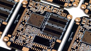
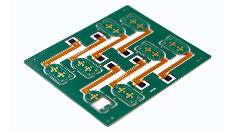
From the perspective of our PCB manufacturing industry, the ingenuity of rigid-flex PCB lies in the material-level combination: the rigid PCB of the load-bearing components and the main circuits usually adopt sturdy boards like FR-4; For the dynamic parts that require bending and twisting, high-reliability materials such as flexible polyimide (PI) are used. Through precise craftsmanship, they form an integrated and inseparable complete circuit system.
The core value of this architecture lies in enabling electronic design to break free from the constraints of the “plane”. It not only provides a “skeleton” for installing chips and withstanding stress, but also endows “joints” for connecting three-dimensional space. This is precisely the fundamental answer to the current demand for compact and highly reliable electronics.
Nature of rigid-flex PCBs:
- Rigid sections support high-density component placement and mechanical durability, ideal for connectors, ICs, and heavy SMDs.
- Flexible areas (flex) permit bending, folding, and dynamic movement without loss of electrical continuity or reliability.
Key Construction Features
Common Rigid-Flex Stack-Up Example
| Section | Material | Functionality | Typical Use |
| Rigid | FR-4, FR-5 | Support, component mounting | ICs, BGAs, connectors |
| Flex | Polyimide (PI) | Dynamic or fixed bend areas | Hinges, wearable sensors, buttons |
| Copper | RA/ED copper | Electrical conductivity | Signal, power, ground planes |
| Coverlay/Mask | PI/epoxy layers | Moisture, abrasion resistance | Flex area insulation, solder mask |
| Stiffener | FR-4/PI/Stainless | Mechanical strength (selective) | ZIF/edge contacts, flex joint ends |
Why Not Use Just Rigid or Just Flexible PCBs?
- Standard rigid PCB assembly is inexpensive for planar, non-flexing products but fails in high-vibration or dense, 3D packaging.
- Flexible circuits alone lack the mechanical backbone for complex assemblies or fine-pitch, heavy components.
- Rigid-flex board assembly allows robust routing, three-dimensional interconnect, and dynamic or repetitive bending all in a single, easily manufacturable system.
Key Benefits & Strategic Value of Rigid-Flex PCB Assembly

Why Choose Rigid-Flex Over Standard Rigid Assemblies?
Advantages of rigid-flex:
- Reliability: Eliminates the need for fragile connectors and solder joints between PCBs—dramatically reducing defect rates and field failures.
- Miniaturization: Enables packing more function in less space, as traces can run between rigid and flexible layers on multiple planes while eliminating wire harnesses.
- Improved assembly process: Lower assembly time, fewer parts, and step reduction in the overall pcb manufacturing and assembly workflow.
- Enhanced performance: Fewer interconnects maintains signal integrity, reduces impedance discontinuity, and allows for continuous ground planes.
- Thermal management and resistance: Better withstands thermal shock, repeated flexing, and CTE (thermal expansion) differences.
- Design integration: Shields, antennas, sensors, or actuators can be embedded into the stack, thanks to the combination of rigid and flexible circuits.
Rigid-Flex vs. Traditional Rigid PCB Assembly
| Feature | Traditional Rigid Only | Rigid-Flex PCB Assembly |
| Connectors Needed | 2-5+ | 0-1 |
| Field Failure Rate | 1-2% | <0.1% |
| Product Thickness | 4-6 mm | 1-2.5 mm |
| Assembly Steps | 4-6 | 2-3 |
| Weight | Heavier | Lighter |
| 3D Routing | Not possible | Integral |
| Serviceability | Complex | Simplified |
Where Rigid-Flex Boards Offer the Most Value
- Aerospace: Lightweight, vibration and shock resistant. Survive extreme temperature cycles while providing robust interconnect between navigation, displays, and controls.
- Medical devices: Implantable monitors, hearing aids, and wearables must survive flexing, sweat, and dynamic movement—rigid-flex is often the only solution.
- Automotive: Advanced driver assistance modules and infotainment edge connectors need to withstand both vibration and temperature swings.
- Consumer electronics: Foldable, wearable, and miniaturized products demand the tight integration and flexibility found only with rigid-flex board assembly.
Material Selection & Pre-Manufacturing Design Principles
The Foundation of Successful Rigid-Flex
Excellent rigid-flex PCB design starts with picking the right materials for your product’s mission.
- Rigid materials: FR-4 or FR-5 for most typical needs; use high-Tg grades (170°C+) for harsh environments or applications requiring enhanced thermal management, such as aerospace or automotive electronics.
- Flexible materials: Polyimide (PI) films dominate due to their superior mechanical stress tolerance, resistance to chemicals, and high-temperature stability.
- Copper selection: Use rolled annealed (RA) copper for flexible areas to maximize flex life (critical for zones subject to repetitive bending).
- Stiffeners and adhesives: Stiffeners—FR-4, PI, or stainless steel—reinforce areas under connectors or critical SMDs in the flex. Acrylic or epoxy adhesives bond between layers but must be chosen for temperature, flexibility, and chemical compatibility.
Tips for Material Selection and Assembly Process:
| Core suggestions | Key actions and considerations | The support that LHD TECH can provide |
| Early design collaboration | Before the layout solidifies, share the initial stack structure diagram with the manufacturer for manufacturability analysis. | Provide manufacturability design reviews, optimize the lamination, bending radius, and the thickness ratio of conductive/insulating layers from a process perspective, and enhance reliability and yield at the source. |
| The zoning and protection are clear | Clearly define the rigid zone, flexible zone and reinforcement zone, and plan the positions of the covering layer window and the solder mask window. | Based on your design, we recommend a verified material combination scheme (such as PI type, adhesive, reinforced sheet material), and review the window design to ensure the best balance between pad protection and solderability. |
| Pre-confirmation of compliance | It is clearly required that all base materials, adhesives, coatings and other materials must comply with the regulations of the target market such as RoHS and REACH. | The supply chain provides a complete set of compliance materials and can offer compliance declaration documents for key materials along with the board, ensuring the smooth certification of your products. |
DFM and Board Layer Planning
The core idea can be summed up in one sentence: When designing, one should think like a factory master and step of the design.
- From the moment of drawing the schematic diagram and arranging the components, one has to start aligning with the manufacturing capacity of the factory. It is essential to clearly and explicitly mark in the document which layers are hard and which are soft.
- Complex design, directly provide a 3D “stereoscopic instruction manual”.If it is a hard-flexible composite plate with a relatively complex structure, it is best to provide a 3D simulation drawing with a bending effect and the minimum bending radius. This is equivalent to giving the factory a “three-dimensional construction drawing”, and they can immediately know how to arrange fixtures and production processes at a glance.
- Component placement: Remember the principle of “return to the hard area and heat to the hard area”. All heavy and highly heat-generating components must be properly placed on the hard part of the board. The soft parts are for bending, not for carrying heavy objects or serving as “heat sinks”.
The Rigid-Flex PCB Assembly Process: Step by Step
| Link | Core objectives and key measures |
| 1.Design and document review | Objective: To ensure that the design is manufacturable and assemblable • Early collaboration: Before manufacturing, manufacturability review must be conducted based on the complete Gerber/ODB++ file, with a focus on the through-hole spacing at the rigid-flexible junction (it is recommended that the distance from the transition zone be ≥1.27mm). • Simulation assistance: Conduct simulation verification on mechanical bending, interlayer alignment, and key signal impedance to avoid risks in advance. |
| 2.Humidity control | Objective: To prevent delamination or cracking caused by moisture absorption of the material • Pre-baking: Flexible substrates (such as polyimide) must undergo high-temperature baking before assembly to thoroughly remove moisture. • Moisture-proof throughout the process: Assembly must be completed within the specified time limit after baking. Semi-finished products must be stored in a dry environment, and the humidity in the workshop must be strictly monitored. |
| 3.Lamination and porosity | Objective: To achieve a stable combination of rigidity and flexibility as well as reliable interconnection • Precise bonding: Strictly follow the lamination plan for bonding, control temperature and pressure, and prevent glue overflow or weak bonding. • Differentiated hole-making: Laser drilling is recommended for flexible areas and high-density interconnections, while mechanical drilling can be used for rigid areas. • Uniform electroplating: Ensure uniform copper thickness within the hole to avoid reliability risks caused by uneven copper plating. |
| 4.Welding and reflow | Objective: To achieve precise assembly with high yield • Specialized carriers: Custom carriers or vacuum fixtures are used to support the flexible parts, ensuring flatness during printing and surface mount. • Customized process: The surface mount technology (SMT) process needs to be adjusted according to the height difference of the board surface. The reflow soldering curve should adopt a gentle temperature rise to manage the difference in the coefficient of thermal expansion between materials and prevent delamination. |
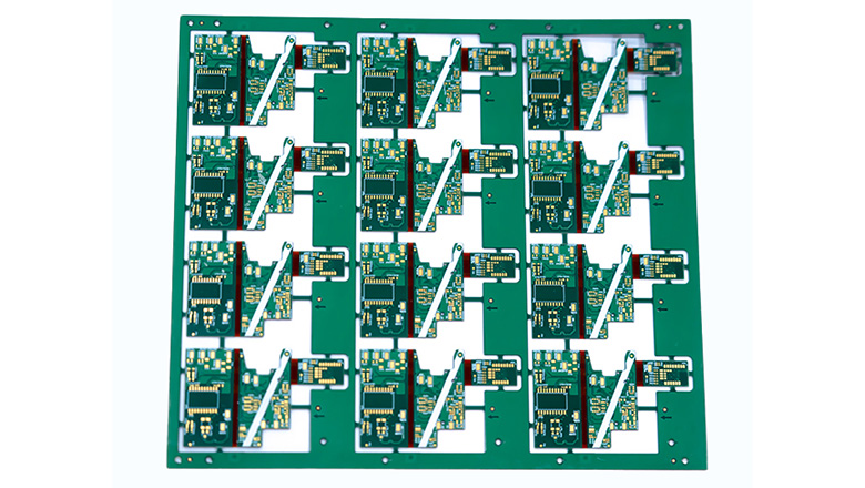
| 5.Panel separation | Objective: To achieve non-destructive separation • Method selection: Plate separation must only be carried out in rigid areas. It is recommended to use precision milling cutters or laser cutting. • Design support: The panel connection points (stamp holes or bridge connections) should only be designed in rigid areas, and it is absolutely forbidden to directly apply stress to flexible parts. |
Unique Challenges of Rigid-Flex Board Assembly
Common Defects and How to Mitigate Them
- Delamination: Driven by poor moisture control or uneven lamination. Mitigated by stringent pre-bake, material selection, and manufacturer’s thermal profiles.
- Barrel cracks & via failures: Occur from thermal expansion/contraction or bending at transition zones. Prevent via placement near flex-rigid boundaries and comply with minimum bend radius best practices.
- Solder joint cracking: Caused by mechanical stress during forming or assembly. Reinforce with stiffeners and validate with thorough mechanical and environmental testing.
- Impedance discontinuity: Can happen when traces cross from rigid to flexible areas without careful stackup and width adjustment. Plan impedance-critical nets during pcb design and validate through simulation and measurement.
Mechanical Stress & Thermal Expansion
- The curved part is the “weak link”
- The core issue is that each time the line is bent, the stress is concentrated locally, especially at the junction where the line “transitions” from the hard zone to the soft zone. It’s like repeatedly bending a straw; the crease is the most prone to damage.
- Countermeasures: When designing, the bending radius must be made as large as possible, and it is necessary to avoid placing through holes or devices in the transition zone to ensure a smooth stress transition.
- The pace of thermal expansion and contraction of the material is inconsistent
- The core issue: The several materials that make up the board (hard FR-4, soft polyimide, copper foil, adhesive) expand to different magnitudes and speeds when heated.
- Serious consequences: If the process is not handled properly, the internal components will “pull each other” when the temperature changes, leading to delamination, bubbling or circuit breakage.
- The key to solving the problem: One of the core goals of the entire manufacturing process is to enable material selection and process control to “work in coordination” and reduce internal friction.
- Rely on “sharp eyes” to identify problems in advance
- Core approach: Advanced detection methods must be used to identify defects at an early stage.
- AOI (Automatic Optical Inspection) : Just like “industrial CT scanning”, it can quickly detect physical defects such as appearance deformation and misalignment.
- Flying probe testing: Like a sensitive “probe finger”, it can precisely measure electrical performance and detect tiny circuit cracks or poor soldering.
- The ultimate goal: The combination of these two is to intercept problems before they occur or leak out, which is a key quality inspection defense line to ensure the reliability of hard-flexible composite boards.
Integration Constraints
- Never mix incompatible flex and rigid adhesives; always consult the fabricator about bonded material stacks for each section.
- Before delivering the design, it is necessary to conduct a complete “rehearsal” of the real assembly and bending process of the circuit board in the entire machine with software to ensure that it can withstand various stresses and disturbances in actual use. The core objective is to expose the problem in the computer simulation rather than in the customer’s factory or market complaints.
DFM Guidelines for Successful Rigid-Flex PCB Assembly
Key Design and Assembly Tips
- Step of the design: Engage your manufacturer in early-stage design reviews—ideally, after the first complete guide to rigid-flex iteration.
- Minimum bend radius: For static bends, at least 5x the total flex thickness; for dynamic bends, at least 10x is best practice to ensure reliability.
- Component placement: Keep high-mass or heat-prone components away from transition zones and bends; always reinforce with stiffeners when SMDs are required in flex.
- Curved trace routing: Instead of right-angle corners, route traces on flexible sections using smooth, gradual curves to prevent conductor fracture.
- Hatched copper planes: Use these in flex areas rather than solid fills—improves flexibility and avoids delamination in tight bends.
- Panelization: Only connect arrays at rigid sections; never stress or perforate flex areas.
Do’s & Don’ts Table:
| Do | Don’t |
| Use hatched copper in flexible areas | Place vias/components in active bends |
| Extend stiffeners beyond pad edges | Route traces perpendicular to bends |
| Mark all keepouts/stackup transitions on fab docs | Leave transitions to assembler alone |
| Test dynamic forming on first prototypes | Rely on simulation alone |
Verification
- Use coupons and witness samples to validate the combination of rigid and flexible materials once the design process is complete.
- Not only should computer “simulation tests” be conducted, but also every step of the actual production process of the circuit board, including bending and installing it into the equipment, should be recorded. Then, through simulation analysis, ensure that the “hard” and “soft” parts are seamlessly combined and sufficiently reliable. Guide the “virtual” simulation with the “real” records, and then verify the reliability of the “real” with the “virtual” simulation, forming a closed loop to ensure that the product does not “fail” in real use.
Testing, Inspection & Quality Control
- Automated optical inspection: AOI is mandatory for all completed assemblies, with scripts tailored to recognize flex/rigid transitions and unique pad designs.
- Flying probe testing: For electrical continuity in complex rigid-flex, flying probe testers can scan for signal breaks, unexpected shorts, or solder defects across rigid and flexible areas—even with varying bend shapes.
- Mechanical testing: Bend-cycle (1,000+ cycles for most wearables/medical), peel strength, and pull tests are performed to match application requirements.
- Thermal cycling: Sample units are cycled between extreme temperatures to mimic real-world shock in aerospace, defense, or automotive.
Cost vs. Reliability in Rigid-Flex PCB Solutions

Full-Cost Analysis
- Integration saves effort and production is faster:It has transformed multiple independent circuit boards that originally required numerous connectors and cables to assemble into an integrated “single board”.
- Sturdy and durable, requiring less repair:The greatest advantage is the leap in reliability. Traditional connectors, solder joints and mechanical interfaces are precisely the parts of electronic products that are most prone to failure.
- Save money on after-sales service and have a better reputation:Based on the above point, the maintenance, replacement and support costs of the product during the warranty period will naturally decrease.
Applications and Industry
Rigid-flex PCB assembly is now central to the most demanding electronics markets. Here’s how it powers success across key industries—each with unique constraints for pcb design, reliability, and the assembly process.
Consumer Electronics & Wearables
- Smartwatches, AR glasses, and foldable phones: By tightly squeezing a bunch of necessary circuits into that extremely limited arc-shaped or irregularly shaped space, it can act like a bridge, connecting the core components such as screens, batteries, and sensors, which are scattered in different planes, into a whole in a “meandering” manner, bidding farewell to the rigid straight-line connections. Moreover, the precision components such as chips are firmly fixed in the hard area, achieving reliable connection of the screen, motherboard and battery when folded.
Medical Devices
- Implantable monitors, nerve stimulators, portable diagnostic: devices Core requirements: Withstand thousands of bends and endure rigorous sterilization and disinfection processes to ensure reliability in extreme environments.
Aerospace & Defense
- Radar payloads, control surfaces, and avionics modules: Under the premise of extreme lightweight, it should cope with drastic temperature differences and complex electromagnetic environments, and meet the highest level of long-term reliability standards.
Automotive
- ADAS, BMS, and infotainment backplanes: Resist continuous vibration and significant temperature changes, reduce connectors and wiring harnesses, and enhance system integration and production yield.
Industrial and Robotics
- Robotic arms, vision systems, and dynamic machinery: It operates stably through continuous movement and repeated bending, achieving three-dimensional wiring and efficient space utilization.
Future Trends in Rigid-Flex Technology
1. More Complex Rigid-Flex and HDI Structures
- More complex cores: To meet the demands of high-end mobile phones and military equipment, today’s multi-layer boards are like building high-rise buildings.
- “Minimally invasive surgery” : It employs precise techniques such as micro-holes, embedded holes, and superimposed holes to achieve interlayer interconnection in an extremely small space.
- “All-rounder” : To handle both high-speed signals (such as 5G data) and high-power currents (such as power supply) simultaneously, the design difficulty is extremely high.
- Evolving into a “system-level” board: The rigid-flex board is no longer just a connecting component; it is almost turning into a “Lego system” on its own. On a single board, it can be fused simultaneously:
- Hard areas (for placing core chips), soft areas (for bending connections), areas for embedding components (to save space), and even directly integrated into the wireless antenna area. This is called “board-level system integration”.
2. Eco-Friendly Manufacturing & Smart Factories
- “Greener” : In line with environmental regulations and brand requirements, factories now generally use lead-free, halogen-free and recyclable materials for production.
- “Be smarter” : Factories are becoming “intelligent”. It is specifically manifested as
- AI quality Inspector: AI-driven optical inspection can detect defects faster and more accurately than the human eye.
- Automated assembly line: Fully automatic surface mount technology (SMT) production lines reduce human errors.
- Predictive AI: Utilizing machine learning algorithms to analyze data and predict potential defective links in advance to prevent problems before they occur.
- The final result: The boards made in this way have better consistency, faster speed and more stable quality.
3. Extreme Reliability & Testing
- With demand for spacecraft, medical, and automotive “zero field failure” rates, rigid-flex PCB design increasingly includes:
- Real-time bend/flex sensing,
- Embedded trace monitoring,
- Serial number and traceability tracking from fab to field.
4. Advanced Integration
- Future rigid-flex technology will support on-board ultrafast interconnects (25+ Gbps), integrated photonics, and multi-sensor arrays all within a single assembly.
- Designs will further leverage smart fabrics and transparent display integration using the principles outlined in this comprehensive guide.
LHDPCB: Your Partner for Successful Rigid-Flex PCB Assembly

Why Choose LHDPCB?
- Full stack expertise—from design consultation and DFM review to complex rigid-flex fabrication and robust board assembly.
- Manufacturing process of rigid-flex is performed with in-house AOI, X-ray, flying probe, impedance measurements, and environmental testing.
- Rapid prototyping—upload your Gerber at any design process step and get feedback on manufacturability within 24 hours.
- IPC-certified reliability and extensive track record in aerospace, medical, and consumer applications.
Frequently Asked Questions
What is the most common defect in the process of rigid-flex?
- Delamination from improper bonding between rigid and flexible layers, often due to moisture, insufficient bake, or mismatched adhesives. Prevented with strict process controls and QA.
How do you maintain signal integrity across both rigid and flexible sections?
- Use controlled impedance traces, avoid tight bends, and ensure consistent copper thickness and stackup. For high-speed, always simulate and test after fabrication.
Can you manufacture any rigid-flex board shape or size?
- Modern PCB manufacturing capabilities support complex geometries, but extremely tiny, ultra-long, or irregularly shaped boards may need special review. Always coordinate early with your pcb manufacturer.
Why is rigid-flex more reliable than traditional rigid or pure flex?
- It combines the strength and connector-mounting capability of rigid with the adaptability of flex—fewer points of failure, reduced solder joints, improved mechanical stress tolerance, and better thermal management.
What is the best way to start a successful rigid-flex project?
- Use this complete guide to rigid-flex as your foundation: document your application’s needs, use a proven DFM checklist, consult your board assembly partner early, and validate with mechanical and electrical testing.
Conclusion: Your Path to Successful Rigid-Flex
In our view at LHD TECH, rigid-flex panels are no longer merely a technical option but the core cornerstone that truly drives product innovation. From the sophisticated and complex space satellites to the reliable and close-fitting medical wearable devices, there is always its presence behind them.
We have found that a successful Rigid-flex PCB assembly is never merely about “making the board”. It concerns the perfect combination of three things:
- A profound understanding of materials – not just about selection, but also knowing how to match and handle them.
- Infuse manufacturability thinking from the very beginning of the design – to ensure that excellent ideas can be stably realized.
- Establish truly transparent collaboration with manufacturing partners – working side by side to address both expected and unexpected challenges.
When we do all these together, what you get will be far more than just a circuit board. Rather, it is a system-level solution that comprehensively surpasses traditional rigid solutions in terms of reliability, space utilization and performance.What we focus on is precisely helping you make this crucial leap from design to reliable mass production that is a unmatched reliability .