
Introduction
Printed circuit boards (PCBs) are core components of most modern electronic products. Smartphones, computers, medical devices and cutting-edge aerospace equipment rely on them to enable efficient circuit design, performance optimization and large-scale production. Diverse application requirements have driven the development of various PCB types. Project developers must select the appropriatePCB type accurately based on specific technical specifications and product requirements.
This guide provides a comprehensive overview of the specific categories of printed circuit boards. These types include single-sided and double-sided boards, as well as multi-layer boards, rigid boards, flexible boards and rigid-flex boards. The guide also explains the design methodologies and manufacturing materials used for printed circuit boards. It further offers practical guidance on board selection for real-world projects. Design engineers require mastery of this knowledge. Electronics enthusiasts likewise need to understand this content. Various professionals involved in the PCB assembly process must also clarify the characteristic differences among different circuit boards. This understanding forms the foundation for achieving reliable operation of electronic products and is key to obtaining high-performance electronic devices.
What Is a Printed Circuit Board?

A printed circuit board (PCB) is a flat board that physically supports and connects electronic components using conductive traces and components—thin lines of copper and other conductive materials—bonded onto an insulating material called the substrate. Instead of traditional wiring, PCBs consist of interconnected circuit pathways etched onto their layers, which deliver both mechanical strength and electrical connections between different components on the board.
PCBs are widely used because they standardize circuit construction, simplify manufacturing and enable mass production of electronic products. They’re the backbone for everything from simple toys to complex control systems in aircraft.
PCBs at a Glance
- PCBs are designed for efficiency, durability and space-saving.
- They consist of at least one layer of conducting material and one or more layers of insulating material.
- PCBs can be as simple as a single layer of conductive material or as complex as multi-layer pcbs with dozens of stacked layers.
- Modern PCB boards incorporate advanced features like rigid-flex pcbs, hdi pcbs and embedded components.
Why Are There Different Types of Printed Circuit Boards?
The electronics industry requires diverse types of printed circuit boards to address multiple challenges, including high-density component interconnection, system thermal management, high-speed signal integrity, mechanical robustness and production cost control. The design of each type of printed circuit board aims to optimize one or more critical performance parameters.
Different types of printed circuit boards include:
- Single-sided boards:Simplest, one side of the board with copper.
- Double-sided pcbs:Traces on both sides, allowing components on both sides.
- Multi-layer pcbs:Multiple layers of traces, separated by insulating sheets.
Main types of printed circuit boards exist because:
- Some applications need flexibility (wearable devices need flexible circuit boards).
- High-speed data needs controlled impedance and multi-layer.
- Harsh environments need ultra-durable materials (e.g., metal core boards in LEDs).
- Complex products need to save space and add reliability (rigid-flex boards).
Main Types of Printed Circuit Boards
We will conduct in-depth breakdown and analysis of the main types of printed circuit boards (PCBs) and comprehensively sort out the composition characteristics of the layer structure, the specific scope of applicable scenarios and the prominent manifestations of core advantages for each type.
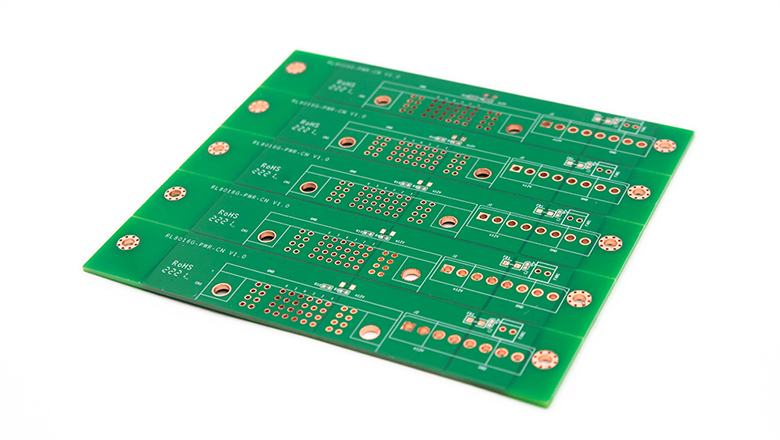
1. Single-Sided PCBs
Single-sided pcbs are the simplest form of circuit board. They consist of a single layer of conductive material (usually copper) on one side of the base material. All circuit traces and electronic components are mounted on this one side of the board.
Key Features:
- Low cost.
- Easy to design and manufacture.
- Ideal for simple, high-volume applications.
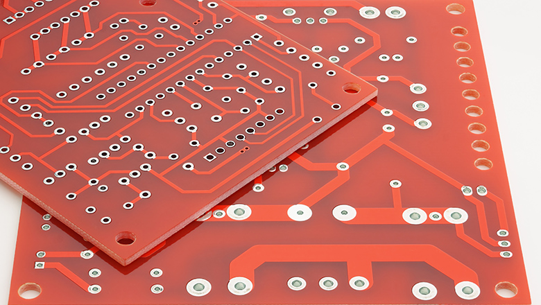
2. Double-Sided PCBs
Double-sided printed circuit boards feature conductive traces distributed across both their top and bottom surfaces. This physical structure enables engineers to mount electronic components on both sides of the board. The board utilizes plated through-holes as connection media. These vias establish electrical connections between the conductive traces on the two surfaces. Ultimately, this design allows complex circuit systems to be laid out within physically constrained spaces.
Key Features:
- Components on both sides of the board.
- Increased density and design flexibility compared to single-sided.
- Better suited for circuits requiring more connections.
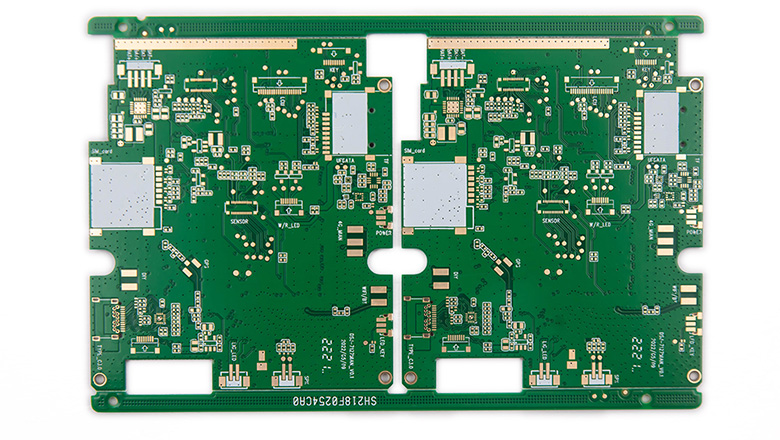
3. Multi-layer PCBs
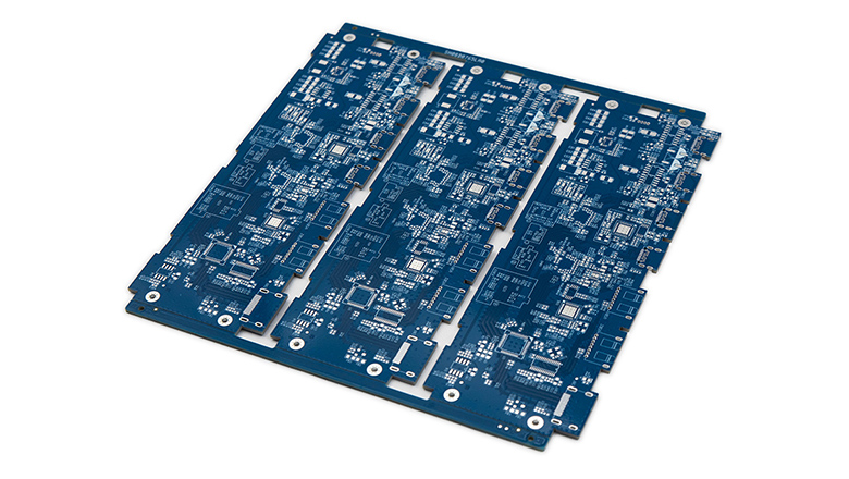
Multi-layer pcbs (also spelled multilayer pcbs) are intricate boards with three or more copper layers, each separated by insulating material. These types of printed circuit boards are used when simple or double-sided designs can’t meet the increasing complexity of multi-layer pcbs in today’s electronics.
Key Features:
- Support for high component density and complex circuits.
- Enhanced signal integrity due to dedicated ground/power planes.
- Reduced electromagnetic interference (EMI).
4. Rigid PCBs
Rigid printed circuit boards are the most widely used type of circuit boards. This type of board is manufactured using non-bendable substrate materials. FR-4 epoxy fiberglass board serves as a representative type of such substrate. The properties of rigid materials enable the circuit board to maintain its original shape when subjected to bending forces. This characteristic also provides reliable mechanical support for the electronic components mounted on the board.
Key Features:
- Not bendable (circuit board that cannot flex).
- Durable and reliable.
- Cost-effective for mass production.
5. Flexible PCBs
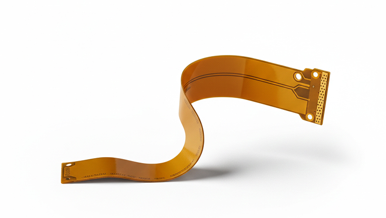
The manufacturing of flexible circuit boards utilizes flexible polyimide or other polymer materials as the substrate. This design approach enables the circuit boards to achieve bending and folding physical forms. In terms of specific structure, engineers can design them into single-layer, double-layer or multi-layer configurations.
Key Features:
- Bend, fold or twist to fit compact spaces.
- Lightweight, space-saving.
- Resist vibration and movement.
6. Rigid-Flex PCBs
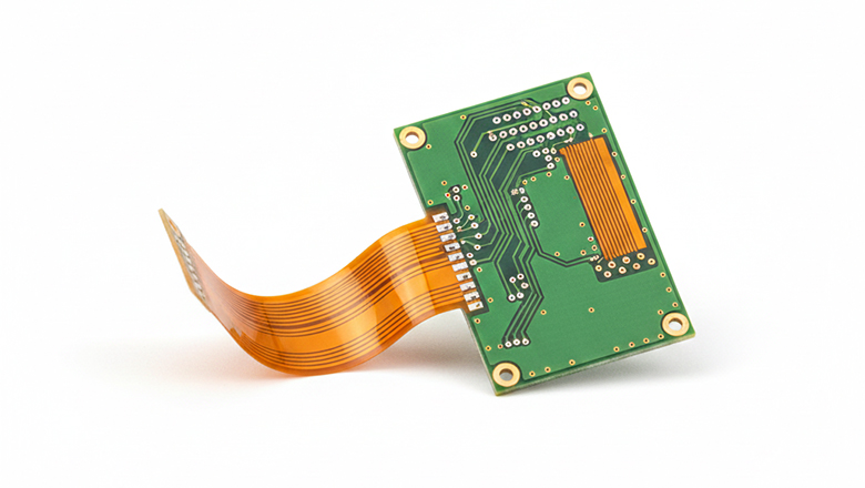
Rigid-flex circuit boards are a special type of printed circuit board. They integrate both rigid and flexible regions within a single circuit board structure. This hybrid design supports three-dimensional packaging solutions, enabling designers to fold and perform shape customization on the circuit board within compact device enclosures.
Key Features:
- Combine the benefits of rigid and flexible pcbs.
- Reduce connectors and cables inside a device.
- Enhance reliability, shock and vibration resistance.
7. Metal Core PCBs
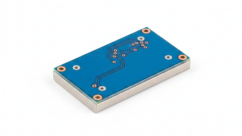
Metal substrates utilize aluminum-based or copper-based materials. These two types of metal substrates replace traditional insulating boards. This structural design achieves efficient thermal management. It enables the rapid dissipation of heat generated by high-power components during operation. Effective heat conduction significantly enhances the operational reliability of electronic components.
Key Features:
- Excellent thermal conductivity.
- Ideal for high-current and LED circuits.
8. HDI PCBs

High-Density Interconnect printed circuit boards utilize microvias and advanced stacking technology. This design approach enables the accommodation of more circuits within a confined space. These circuit boards hold indispensable importance in miniaturized high-speed devices.
Key Features:
- Miniaturization, fine pitch components.
- High circuit density.
Structure and Layers of PCB Boards
The functional realization of all printed circuit boards relies on their core structure and layered design. Whether single-sided, double-sided or multi-layer boards, their functionality and long-term durability depend on the core structure and layered design. Specifically, the number of layers included in the circuit board is a critical factor. The stacking method of signal layers and insulating layers is another determining factor. The connection process between layers is also crucial. These factors collectively determine the final performance of electronic products. They also affect the manufacturability of circuit board production and the overall cost of the project.
Anatomy of a PCB
Regardless of the type of pcb, all boards are constructed from these basic layers:
| Layer | Description |
| Silkscreen | Printed reference marks for components on the board |
| Solder Mask | Protective layer on top of copper to prevent short circuits |
| Conductive Layer | Copper traces form the actual circuit pathways |
| Base Material (Substrate) | Main insulating material (FR-4, polyimide, metal core, ceramic) |
| Components Layer | Where electronic components are mounted |
| Surface Finish | HASL, ENIG, or OSP to aid in soldering and reliability |
Single-Sided Boards
- Consist of a single layer of copper on top of the substrate.
- Used for the simplest circuit and low-cost products.
- All electronic components are mounted on one side.
Double-Sided Boards
- Features conductive traces on both the top and bottom surfaces.
- Components on both sides boost circuit complexity and density.
- Vias provide electrical connections between different layers.
Multilayer PCBs
- Multiple layers of conducting material separated by insulation.
- Main types of printed circuit architecture for high-speed, high-density circuits.
- Boards include internal power and ground planes to improve performance and control EMI.
- Can consist of 3–50+ different layers, depending on complexity.
Key PCB Materials Used
The selection of PCB materials is a critical step in ensuring circuit board performance. Choosing the appropriate PCB material is essential for its electrical performance, mechanical strength and thermal management capabilities. During the manufacturing process, circuit boards typically employ special materials with low dielectric loss. This material characteristic ensures the reliability of the signal transmission process while also supporting the circuit board in achieving a longer service life.
Common PCB Base Materials
| Base Material | Properties | Applications |
| FR-4 | Fiberglass-epoxy, low cost, good strength, standard choice | Rigid pcbs, most consumer/industrial |
| Polyimide | Flexible, high temp, good dielectric | Flexible pcbs, rigid-flex boards |
| Aluminum/Copper | High thermal conductivity, robust | Metal core boards, LEDs, power circuits |
| Ceramic | High thermal/electrical performance, chemically inert | Automotive, RF, aerospace |
| PTFE, Rogers | Low dielectric, high frequency, minimal signal loss | HDI, RF, 5G, and satellite circuits |
| CEM-1/CEM-3 | Paper or glass/epoxy, economical, simple circuits | Low-cost, low-complexity pcb boards |
PCB Design and Manufacturing Considerations
Effective pcb design and manufacturing determines the success and reliability of your electronic products. Every decision—from layer count and materials to trace width—affects the circuit board’s performance and manufacturability.
Key Design Considerations
- Component Placement: In the design process of multi-layer printed circuit boards, engineers must rationally plan the layout positions of electronic components. This layout principle aims to achieve shortened and direct signal paths. The optimization of signal paths plays a critical role in ensuring signal integrity.
- Signal Routing: During the circuit design phase, engineers need to employ wider traces for power lines. To prevent short circuits, appropriate electrical clearances must be established. In high-speed circuit designs, precise impedance control is essential. Collectively, these requirements ensure the stable operation of the circuit system and maintain signal quality.
- Thermal Management: Circuit board design incorporates multiple heat dissipation technologies. Copper pour areas are used to expand the heat dissipation surface of the board. Thermal vias facilitate heat transfer between different board layers. Metal substrates effectively enhance the overall thermal conductivity of the circuit board. When necessary, engineers install independent heat sinks for high-power components. These technologies collectively work to dissipate the heat generated during the operation of power components.
- Layer Stackup: Determined by the complexity of your circuit. Multi-layer PCBs allow dedicated power and ground planes for noise suppression.
- Manufacturing Constraints: Having a thorough understanding of the manufacturer’s technical specifications is a fundamental step to ensure the success of circuit board design. You must clarify the minimum trace width parameters that the manufacturer can process. It is also necessary to specify the minimum trace spacing parameters they can handle. Furthermore, you need to confirm the range of via sizes that the manufacturer can achieve. Additionally, you should be familiar with the standardized circuit board thickness options they provide. These specific manufacturing capability parameters directly determine the feasibility of the circuit board design.
- Final PCB Assembly: Design for automated assembly processes and consider test-point access for easier verification and debugging.
Common Pitfalls
- Overly dense routing on single or double-sided boards can cause crosstalk and EMI.
- Inadequate via or pad size can cause failures in assembly.
- Poor choice of materials can shorten the lifespan when product operates in harsh environments.
Applications of the Various Types of PCBs
Printed circuit boards are used in nearly all fields of application. Each major type of printed circuit board is specifically optimized to address particular electrical performance requirements, mechanical structural demands and various challenges posed by real-world application environments.
Where PCBs Are Widely Used
- Single-sided boards:Toys, calculators and household gadgets—used in consumer electronics where complexity is low.
- Double-sided pcbs:Appliances, audio equipment and lighting controls—offer greater density.
- Multi-layer pcbs:Laptops, smartphones, networking hardware, servers, military/aerospace equipment—used in advanced, high-speed or high-reliability circuits.
- Rigid pcbs:Mainstream computers, TVs and automotive ECUs—rigid pcbs are used for their strength and reliability.
- Flex pcbs:Wearables, printers and digital cameras—flexible circuit boards fit compact, mobile applications.
- Rigid-flex boards:Aerospace modules, medical implants and rugged industrial equipment—hybrid boards tackle vibration and shape constraints.
- HDI pcbs:Tablets, 5G gear and IoT sensors—miniaturized devices where space and signal integrity are at a premium.
- Metal core boards:LEDs and high-current inverters—perfect for efficient heat spreading.
- Ceramic boards:Car sensors, RF amplifiers, microwave and high-frequency electronics.
Choosing the Right Type of Printed Circuit Board for Your Project
The right board for your project depends on:
- Complexity of the circuit(How many connections? High-speed? Power needs?)
- Required durability, vibration and environmental resistance
- Form factor and available space
- Thermal management or heat-dissipation needs
- Production budget and expected volume
Selection Table
| Application | Recommended PCB Type(s) |
| Simple calculator, toy | Single-sided pcb |
| Consumer appliance | Double-sided pcb or multilayer pcb |
| Smartphone, router | Multilayer, HDI, rigid-flex |
| Wearable, flexible device | Flex pcb, rigid-flex pcb |
| Automotive headlight | Metal core board, rigid pcb |
| RF, radar, 5G device | Multilayer pcb, HDI, ceramic board |
| Medical implant | Rigid-flex pcb, flex pcb, multilayer pcb |
Frequently Asked Questions
Q: What’s the difference between single-sided and double-sided boards?
A: A single-sided pcb consists of a single layer of conductive material with all circuit traces and components on one side of the board. Single-sided boards are constructed for the simplest circuits, where density and complexity are low—often used in cheap electronic products and toys. In contrast, a double-sided pcb has copper traces on both sides, allowing for more compact layouts and more complex circuits by placing components on both sides of the board. Double-sided pcbs have conductive traces connected through vias and they are common in consumer and industrial electronics where space and moderate complexity are required.
Q: How do multi-layer pcbs differ from other common pcb types?
A: Multi-layer pcbs consist of three or more layers of conducting material separated by insulating material sheets. These boards also include dedicated power and ground planes, making them ideal for high-speed, high-frequency or high-density applications. They offer superior signal integrity, reduced electromagnetic interference and higher component density. Used in advanced devices like smartphones, servers and high-speed routers, the complexity of multi-layer pcbs allows engineers to address stringent performance, EMI and layout constraints.
Q: What is a rigid-flex pcb and where are rigid and flexible pcbs combined?
A: A rigid-flex pcb is a hybrid circuit that merges the benefits of rigid pcbs and flexible pcbs. Parts of the board remain rigid, providing sturdy mounting and support for connectors or large components, while flexible areas can bend and flex around corners or fit into compact spaces. This type of printed circuit board is commonly used in aerospace, wearables and medical devices—anywhere a combination of mechanical stability, compactness and flexibility is required.
Q: Why does pcb material matter?
A: The chosen pcb material—such as FR-4, polyimide, ceramic or metal core—affects electrical performance, thermal dissipation, layer count, flexibility and resistance to harsh environments. For example, metal core boards are used in LED lighting for heat dissipation, while ceramic substrates are crucial for high-frequency and high-temperature applications.
Q: Can you summarize the main types of printed circuit boards?
A: The main types of printed circuit boards are:
- Single-sided pcbs (simplest, one side of the board)
- Double-sided pcbs (conductive traces on both sides)
- Multi-layer pcbs (three or more layers)
- Rigid pcbs (non-flexible)
- Flexible pcbs (bendable)
- Rigid-flex pcbs (hybrid rigid and flexible)
- Metal core boards (for heat management)
- HDI pcbs (high-density for miniaturization)
- Ceramic boards (for frequency/thermal extremes)
Q: For advanced applications, what types of printed circuit boards are used?
A: In advanced fields—such as aerospace, 5G, automotive safety and medical devices—engineers rely on multilayer pcbs, rigid-flex pcbs, HDI pcbs, ceramic boards and metal core boards. These different types of pcbs are ideal for applications requiring complex circuits, miniaturization or performance in harsh environments.
Q: What are the most common pcb types found in consumer products?
A: Most consumer products use single-sided boards for basic electronics, double-sided pcbs for moderate complexity (like household appliances) and multi-layer pcbs in smartphones, computers and networking devices.
Q: How does the number of layers affect my design?
A: The number of layers determines how compact, complex or high-speed your pcb boards can be. More layers enable better power distribution, signal integrity and support for high-density designs, but also increase costs and manufacturing complexity.
Q: Are there eco-friendly options in pcb design and manufacturing?
A: Yes, modern pcb design and manufacturing practices include lead-free surface finishes, water-based processing, recyclable materials and modular board designs for easier repair and recycling.
Conclusion and Key Takeaways
The Importance of Understanding PCB Types
Selecting the right type of printed circuit board is crucial for cost, performance, durability and long-term success in electronic products. Thanks to continuous innovation, different types of printed circuit boards can be tailored to suit everything from a child’s toy to a spacecraft guidance system. Knowing the strengths and constraints of each pcb type, from single-sided pcbs to multi-layer pcbs and rigid-flex pcbs, helps you balance electrical needs, physical space and budget.
PCBs are widely used precisely because they’re diverse, scalable and customizable for virtually any purpose in the electronics industry. New trends such as system-in-package, advanced HDI and embedded component boards are paving the way for even more compact and powerful designs.