
Introduction
The inductor symbol is a basic element in all circuit diagrams. It stands for a component that opposes variations in electric current and stores energy within a magnetic field. Inductors will support a wide range of applications, from basic DC chokes and LC filters to complex RF oscillator circuits, it also make many technical innovations possible. Also, proper circuit design and analysis require a solid grasp of the inductor symbol—its is draw one style, physical meaning, and the link between the schematic mark and a real-world inductor.
If you’re an engineering student, to studying passive electrical components, a technician interpreting circuit schematics, or a designer choosing inductors for power supplies, then audio amplifiers, this guide will help us to proficiently read and apply inductor symbols.
What Is an Inductor? (Definition, Function & Applications)
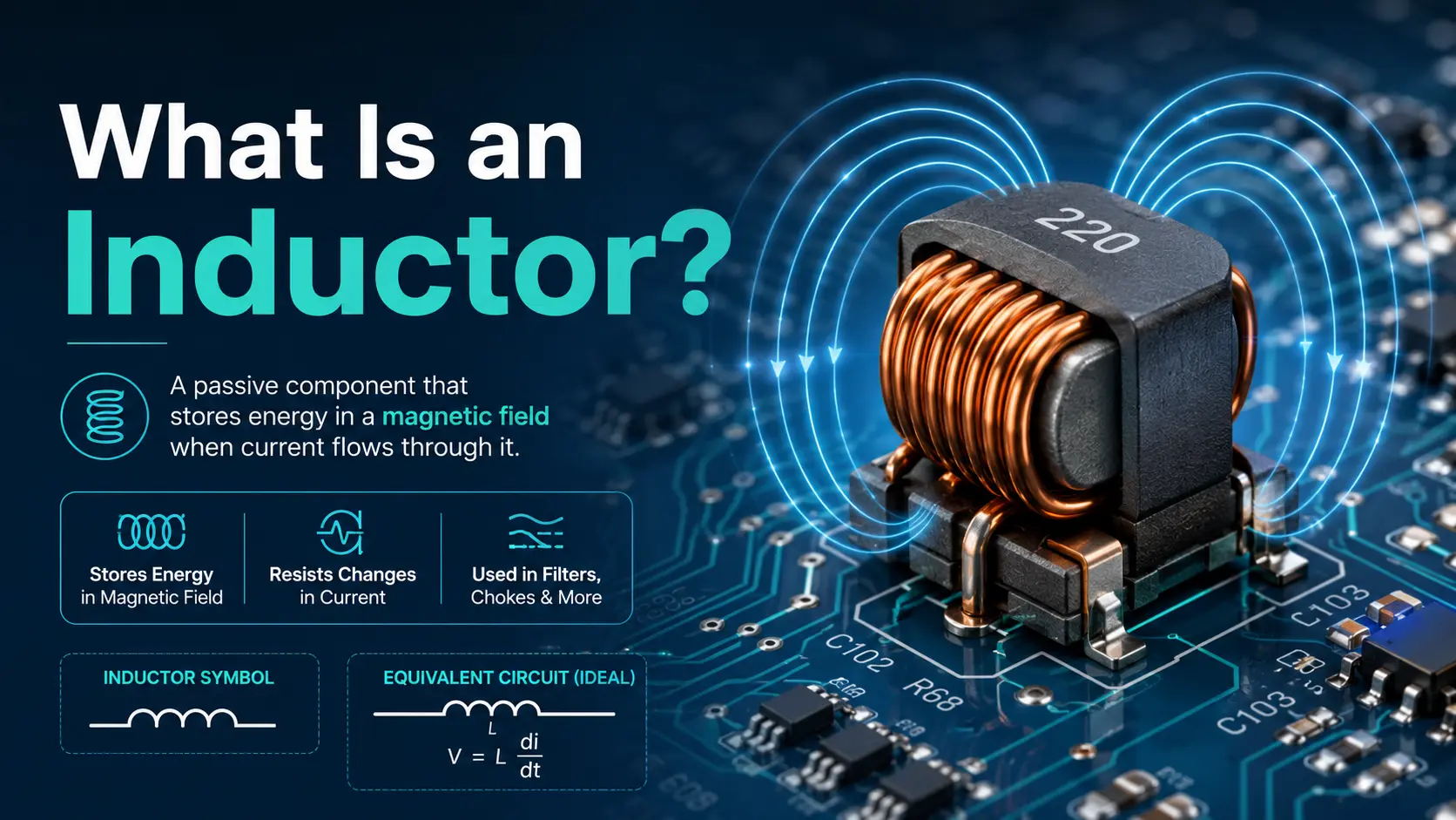
An inductor is a passive two-terminal electrical component It stores the energy as a magnetic field generated by current passing through a coiled wire. Its key is opposing shifts in electric current, it also makes essential for filtering, energy storage and signal tuning.
Key Facts:
- An inductor is a passive electrical component; It absorbs power and cannot generate power.
- Inductance is quantified in henries (H). This property governs how much energy the component stores within its magnetic field when current varies.
- Inductors are typically constructed with coiled conductive wire, most commonly copper. A core made of air, iron, ferrite or other magnetic materials may be added to boost inductance.
Physical Construction and Principle
- The fundamental structure is the coil—the number of turns and the shape of the coil directly affect the inductance value.
- In real inductors, the core material—air core, iron core, ferrite core, or other magnetic core—influences performance, from frequency response to energy storage efficiency.
- Whenever there’s a change in current, the inductor generates a voltage (EMF) that opposes it. This is called self-induction.
Typical Inductor Applications
Inductors are used in circuits to:
- Smooth ripples or AC noise in power supplies (power supply inductor, DC/DC converters)
- Block or pass high-frequency signals in filters (LC filter, RC and RL circuits)
- Tune oscillator frequencies (radio, RF circuits, resonant circuits)
- Store energy temporarily in switching regulators and boost/buck converters
- Act as chokes to block AC while passing DC (choke in power supplies and audio amplifiers)
- Work with capacitors in all kinds of LC circuits—from signal filtering to frequency selection
Inductor Symbol in Circuit Diagrams
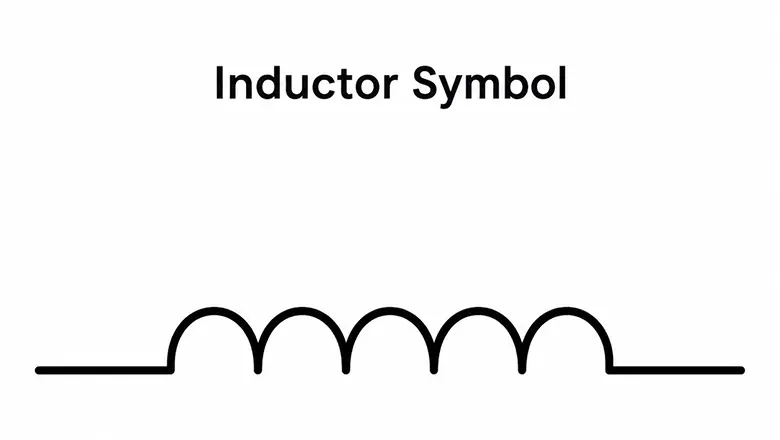
In every circuit schematic, the inductor symbol is visually/functionally links the theoretical design to the real-world hardware implementation. The inductor symbol in circuit diagrams conveys:
- The presence of a coil or winding that opposes changes in current
- Often, the core material or special functionality (iron core, ferrite core, variable)
- The unique reference (L1, L2) and sometimes the inductance value
Why Is the Inductor Symbol a Coil?
The symbol for an inductor is drawn as a series of loops or “humps” because it directly represents the wound wire of actual inductors. The more loops or humps, the greater the visual emphasis on energy storage capability—mirroring how real inductors operate.
How Inductors Work: Principles and Core Concepts

The inductor works based on electromagnetic induction. Current passing through the coil creates a magnetic field that holds electromagnetic energy. When the current fluctuates, the inductor generates a voltage counteracting this variation, which forms the principle of inductive reactance.
Key Working Equations
Voltage Across the Inductor (Lenz’s Law): [ V = L \frac{dI}{dt} ] Where L is inductance (H), (dI/dt) is the rate of change of current. The voltage across the inductor is directly proportional to how quickly the current changes.
Inductor Current Response: [ I(t) = \frac{1}{L} \int V dt ] The current flowing through the coil increases gradually when voltage is applied, and decreases slowly when voltage is removed.
Energy Stored in Inductors: [ E = \frac{1}{2} L I^2 ] Inductors store energy in their magnetic field—fundamental for energy buffering in switching power supplies and DC-to-DC converters.
The Role of Magnetic Core and Inductance Value
The inductance of a coil depends on the number of turns, main material, and the main dimensions of the coil.
- Iron core inductors and ferrite core inductors use magnetic materials to boost inductance, it make compact, high-value coils.
- Air-core inductors rely solely on the winding and are ideal for high-frequency RF circuits, as they eliminate core losses.
Quick List: Effects of Coil Design and Core Material
- More turns of the coil→ Higher inductance
- High-permeability core material(iron core or ferrite core) → Higher inductance value in less space
- Larger coil diameter/length → Greater ability to store energy
- Air core—best for RF, high frequencies, and low core losses
Standard Inductor Symbol: Regional & Standards Comparison
The standard inductor symbol can not only look slightly different depending on whether a circuit schematic adheres to ANSI (American), IEEE, or IEC (European/International) standards.
ANSI/IEEE (American)
- Symbol: A series of “humps” (loops) suggestive of a wire wound coil.
- Variants: Core material indicated as parallel solid (iron core) or dashed (ferrite core) lines next to or within the coil.
IEC (European)
- Symbol: More angular, often a rectangular loop or arc with minimal visual flourish.
- Variants: Core materials and adjustments may be annotated or shown by added lines or dashed line style around the arc.
Why It Matters
With globalization, collaboration, and increasingly digital supply chains, understanding both American and European schematic symbol conventions—especially for the inductor symbol—is central to circuit analysis and hardware interoperability.
Recognizing and Reading Inductor Schematic Symbols
Step-by-Step Guide
Spot the Coil Locate the series of humps/loops or rectangles in the schematic—this instantly marks the component as an inductor.
Check for Reference Label Look for “L1,” “L2,” etc. The “L” stands for inductance.
Identify Core Material
- No added line: Air core inductor (common in RF, high-frequency circuits).
- Solid line(s): Iron core inductor, suitable for power and audio circuits.
- Dashed line(s): Ferrite core inductor, best for EMI filtering, high-frequency and switching.
Spot Adjustments or Taps An arrow: Variable inductor (for tuning). A tap: Specialized for voltage division or multi-winding transformer circuits.
Cross-reference the BOM/Part Spec The schematic label, symbol, and attached notes is directly to the exact part (inductance value, max current, core material, etc.) it used on the printed circuit board.
Dot Convention, Transformer Symbols, and Phase
Coupled inductors—most notably transformers—use dots at points on windings to indicate winding polarity. This is essential for circuit function where phase matters (e.g., in power supplies, amplifier transformers, push-pull and flyback designs).
How It Works
- When direct current (DC) or alternating current flows into the dot of the primary winding, the induced voltage at the secondary winding’s dot is in phase.
- Reversed dots change phase, potentially inverting voltage or causing transformer malfunction.
Example: In a push-pull amplifier’s transformer, failing to observe the dot convention can lead to current flow that cancels, not amplifies, the desired signal—resulting in lost power or distorted audio.
Special Transformer Applications
- Audio Power Transformers: It is critical for matching impedance and max signal in amplifier output stages.
- RF Transformers: It was used for impedance matching and isolation in high-frequency (VHF/UHF) applications.
- Switching Power Transformers: Provide isolated voltage rails in switch-mode power supplies.
Inductor Symbol vs Other Circuit Symbols
| Property | Inductor | Capacitor | Resistor | Transformer |
| Symbol | Coil loops/humps | Parallel lines ( | ) | |
| Energy Storage | Magnetic field | Electric field | None | Mutual magnetic energy |
| Frequency Response | Resists change in current | Resists change in voltage | Constant for all freq. | Frequency-dependent |
| Use/Example | Filters, chokes, amplifiers | Timing, filters, oscillators | Current limiting | Voltage transformation/isolation |
Inductor in PCB Design, Layout, and Assembly

Best Practices
- Footprint Accuracy: Always match the inductor symbol in your schematic to the right surface-mount or through-hole package footprint on your printed circuit board.
- Current Handling: To choose an inductor with an inductance value and a current rating above your circuit’s max instantaneous current—check for “saturation current” and “self-heating.”
- Placement: In power supplies, place inductors close to switching FETs or controllers; in audio amplifiers, minimize trace length to reduce losses.
- Thermal Design: Real inductors dissipate power—ensure good copper to wick away heat, especially in DC-DC converters.
- Component Handling: Ferrite and iron core inductors are often brittle—follow ESD and handling recommendations during assembly.
Tips for Drawing and Annotating Inductor Symbols
Clear, standard schematics are critical for circuit analysis, PCB fabrication and fault diagnosis. Whether you are a student, electronics hobbyist or professional designer, adopting correct inductor symbols and markings helps save time and avoid subsequent mistakes.
Best Practices for Drawing Inductor Symbols
- Use Consistent Humps or Loops: sketch a minimum of three, preferably four smooth loops for standard inductors, mimicking the coil structure of physical inductors. This outline indicates the component is a passive device that stores energy within a magnetic field.
- Core Material Indication:
- Air core inductor: Simple loops, no added lines.
- Iron core inductor: Add two solid parallel lines next to or beneath the coil, indicating the presence of an iron core for boosted inductance.
- Ferrite core: Use a dashed line to represent ferrite material, denoting excellence at high frequencies and EMI suppression.
- Variable Inductor: Place a diagonal arrow through the coil symbol to show variability. This is common in high-frequency oscillator circuits and tunable RF filters.
- Tapped Inductor: Draw a tap line protruding from a midpoint in the coil, showing where an additional conductor connects for multi-winding or impedance matching.
- Transformer: Combine two inductor coil symbols paired, possibly with a magnetic core line and dot convention on terminals to indicate phase and polarity.
Annotation Tips
- Reference Designator: Always use “L” for inductors (“FB” for ferrite beads, “T” for transformers), keeping consistent across schematic and BOM (e.g., L1, L2, FB3, T1).
- Inductance Value: Write the inductance (e.g., 10 μH, 1 mH) next to the symbol for clarity.
- Current and Voltage Ratings: Annotate if critical to design, especially in power electronics or amplifier signal paths.
- Core Notes: Specify “air core,” “iron core,” or “ferrite core” if essential to circuit performance.
Conclusion: Symbol Mastery for Circuit Success
Grasping the inductor symbol and its practical meaning opens up the full scope of energy storage, filtering and frequency control in electronics. Whether you analyze a conventional power supply, develop a high-frequency RF amplifier, or diagnose signal noise, proficiency with schematic symbols guides every stage of your work.
Key takeaways for every engineer, maker, or student:
- Recognize the different types of inductor symbols(air core, iron core, ferrite core, variable, tapped, transformer).
- Annotate core material, inductance value, and polarity when needed.
- Always align schematic design with part selection and PCB layout, especially for high frequency, current, or precision applications.
- A clear, well-annotated circuit schematic is the blueprint for robust, reliable, and innovative electronic systems.
Final Thought: When you see the inductor symbol on a schematic, envision all the electromagnetic power, filtering, and signal purity it governs in your circuit’s performance. Use this knowledge to design smarter, debug faster, alao bring your electronics projects to life with confidence.
Frequently Asked Questions About the Inductor Symbol
1. What is the standard symbol for an inductor?
The standard inductor features a coil-shaped trace between two terminals. It represents the wire winding that generates a magnetic field.
2. Why is the symbol L used for an inductor?
The letter L is the standard symbol for inductance and is commonly associated with Heinrich Lenz. It also avoids confusion with I, which represents electric current.
3. Is inductance represented by L or H?
L represents the inductance value, while H represents the henry, the SI unit of inductance.
4. What is the unit symbol for inductance?
The SI unit symbol for inductance is H. Practical inductor values are commonly expressed in millihenries (mH), microhenries (µH), or nanohenries (nH).
5. How are inductors labeled in circuit diagrams?
Inductors are normally identified by the reference designator L, such as L1, L2, or L3. Their inductance value is usually printed next to the symbol.
6. How can you identify an inductor symbol in a schematic?
Identify the coil-shaped symbol with two terminals. The adjacent reference designator L and inductance rating confirm this component is an inductor.
7. What do parallel lines next to an inductor symbol mean?
Parallel lines next to the coil signify an inductor fitted with a magnetic core, such as iron or ferrite. Symbols without these lines generally stand for air-core inductors.
8. What does an arrow through an inductor symbol mean?
An arrow crossing the coil denotes a variable, or adjustable inductor. Its inductance may be altered via mechanical or electronic means.
9. What is the difference between an inductor symbol and a transformer symbol?
An inductor symbol usually shows a winding. A transformer symbol will show two or more magnetically coupled windings, it often separated by core lines.
10. What do the dots on coupled inductor symbols mean?
The dots indicate the relative polarity and phase relationship between coupled windings. This marking is important when determining voltage direction in transformers and coupled inductors.