
Introduction to PCB and Robotics PCB
In today’s era of advanced automation, the printed circuit board (PCB) is the backbone of every reliable robot and automation system. Whether it’s the precision in industrial robots on production lines, the delicate maneuvering of medical robots, or the efficiency of consumer robotics, robotics PCBs ensure stable performance, robustness, and smart integration of all electronic components.
We present to you this comprehensive guide to help you systematically master the core points of robot PCB design and manufacturing. We will delve deeply into the unique features of robot-specific circuit boards, the engineering challenges faced by the industry, best practices in design and manufacturing, and how to create circuit boards that are both highly reliable and precise – and ensure that their soldering and assembly processes comply with IPC-6012 and IPC-A-600 standards. Whether you are an experienced engineering team or a developer independently advancing a robot project, LHD TECH will assist you in making every informed technical decision, from schematic design to mass production.
What Is a Robotics PCB?
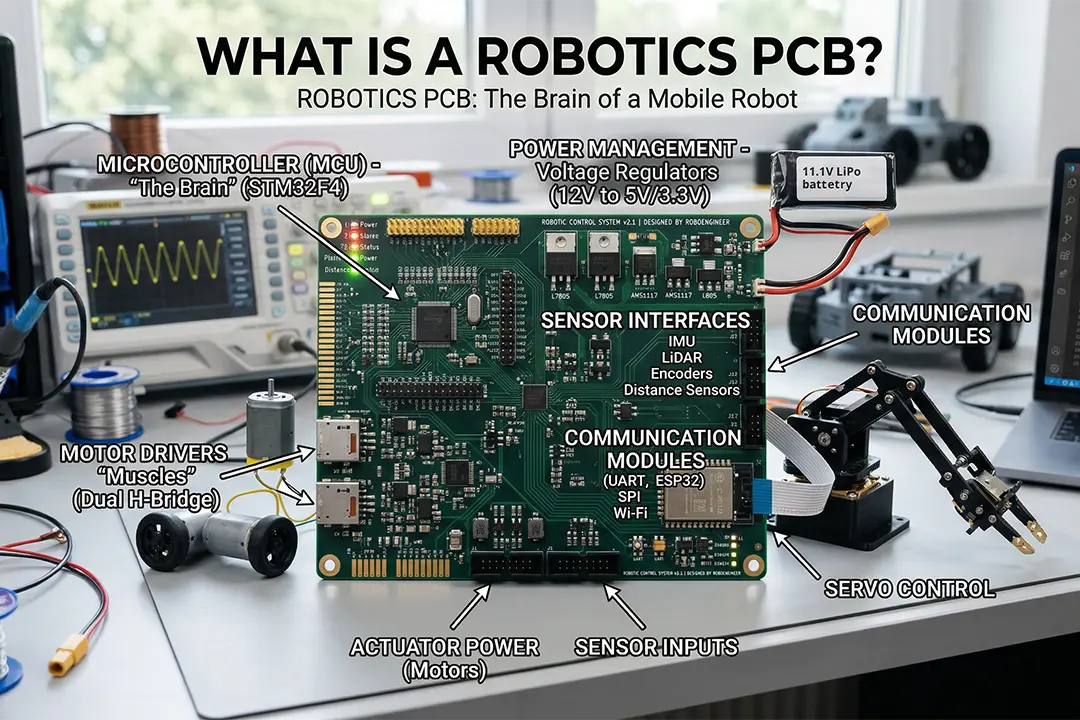
Robot PCB (or robot-specific circuit board) is a type of circuit board specially designed to meet the strict operational requirements of various automation systems. Unlike general-purpose circuit boards, A robotics PCB must have high-density signal interconnection (HDI) capabilities, a precise material selection system, and excellent thermal management performance, so as to achieve long-term stable operation under harsh working conditions. Every robot PCB we design and produce takes high reliability, signal integrity and environmental adaptability as core engineering indicators, providing a solid electronic hardware foundation for automation systems.
Key distinctions for robotics PCBs versus standard PCBs:
- High-precision aspect ratio for drill holes and multilayer designs
- Rigorous adherence to safety standards and the ability to pass industry-specific quality testing
- Materials suited for heat management, signal integrity, and safety-critical automation
Why Robotics PCB Design and Manufacturing Matters in Automation
The design and manufacture of robot PCBS directly determine the reliability, performance ceiling and functional expansion capability of any robot or automation system. If the Design for Manufacturability (DFM) principle is ignored during the design stage, it may lead to costly failures in field applications – such as open circuits, solder bridging, short circuits and other serious defects, which in turn affect the stable operation of the entire system.
High-Reliability Considerations:
- Conforming to established standards: The minimum acceptability of robot PCBS is strictly based on IPC-6012 (Specification for the Acceptance and Performance of Rigid Printed Circuit Boards) and IPC-A-600 (Acceptability of Printed Circuit Boards). These two standards jointly define quantitative indicators ranging from conductor integrity, hole wall quality to lamination defect control.
- Material selection: FR-4 is suitable for most industrial robots and features excellent mechanical strength, electrical insulation and cost-effectiveness. Polyimide is specifically designed for FPC or HDI structures and features excellent flexural life (≥ 100,000 bends), high-temperature resistance (>200°C), and radiation resistance. Rogers high-frequency materials are used in robots that integrate millimeter-wave radars, ultrasonic sensors or high-speed communication interfaces.
- Component placement and orientation: The layout and orientation of components directly affect the reliability of soldering and the long-term service life: SMD adopts a layout principle parallel to the main direction of vibration in the axial direction to reduce stress concentration at solder joints. Anti-vibration pads or underfill adhesives should be added around fine-pitch devices. For heavy-duty components such as connectors, transformers and large capacitors, THT uses reinforced pads, riveting or dispensing for fixation. Heat-sensitive devices should be kept away from heat sources such as power transistors and motor driver ics.
Key Functions of Printed Circuit Boards in Robotics
From simple control systems to high-performance automation, robotics PCBs deliver these core functions:
Control System Integration:
- Integrated application of microcontrollers and FPgas: Robot PCBS achieve high-precision logical decision-making, motion trajectory control, and automated process scheduling by integrating microcontrollers (MCUS) and field programmable gate arrays (FPgas).
- A typical example (medical robot control system) : Its control core adopts a 12-layer PCB dedicated to robots. This design integrates safety-critical redundant paths (such as dual power supply monitoring, independent watchdog) and high-speed sensor feedback interfaces (such as encoders, force sensors, and visual data streams) within a limited space.
Power Distribution and Heat Management:
- Correct trace width sizing for power lines, robust via arrays for thermal dissipation.
- Use of DC-DC converters, LDOs, and power planes for stable power, especially under peak load.
Signal and Data Integrity:
- High-density signal wiring and controlled impedance traces for sensor fusion, often with multi-stage filtering for industrial robots facing massive EMI from production line machinery.
Communication:
- Flexible support for protocols—CAN, SPI, UART, Ethernet, and I2C.
- Integration of wireless modules for remote monitoring in automated and mobile robots.
Types of Robotics PCBs: Choosing the Right Circuit Board
Choosing the right PCB type is key to ensuring system longevity and meeting automation goals in various industries:
| PCB Type | Use Case | Benefits |
| Single-layer | Basic robots, prototyping | Low cost, simple PCB assembly, easy for small-scale or student projects |
| Double-layer | Consumer robots | More routing space, improved signal separation, common in BOMs |
| Multilayer (HDI) | Industrial automation | High-density, robust, optimal for robots with many sensors/motors |
| Flexible & Rigid-flex | Medical/service robots | Superior durability in moving sections, ideal for space-saving designs |
| High-frequency | Drones, autonomous vehicles | Ensures accurate, low-loss high-speed signal transfer |
| Metal-core | Power robotics, lighting | Unmatched heat management for high-power drives & long-term reliability |
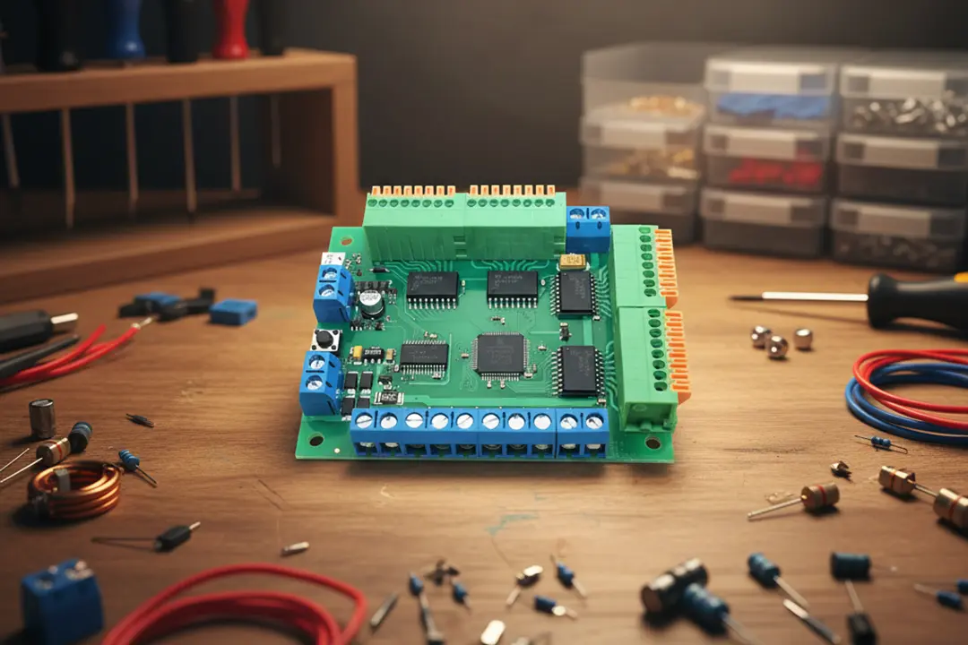
Essential Components and PCB Assembly for Automation Systems
The PCB of a robot needs to highly integrate multiple electronic components and ensure that they work in coordination and operate without failure under stress environments such as mechanical vibration, temperature fluctuations, and electrical noise. Based on the application scenarios of robots, we conduct systematic design and process control for the following key components:
- Microcontrollers and Processing Units: Realize real-time control, logical decision-making and data preprocessing. Industrial-grade robots widely adopt high-performance MCUS such as ARM Cortex-M series or STM32 to meet the requirements of deterministic latency and peripheral interfaces. For scenarios that require processing high-definition camera data, multi-axis synchronous control, or complex motion planning, an FPGA is integrated as a coprocessor to utilize its parallel computing capabilities to complete high-speed data stream processing and closed-loop control.
- Sensors, ADCs, and Signal Conditioners: Sensor types include ultrasonic, photoelectric, temperature, radio frequency (RF), etc. Through circuits such as instrumentation amplifiers, filters, and ADC drivers, weak or noise-sensitive sensor signals are amplified, filtered, level offset, and impedance matched. Differential traces, shielded ground wires and independent analog power planes are adopted to suppress the influence of digital noise inside the PCB on the analog front end.
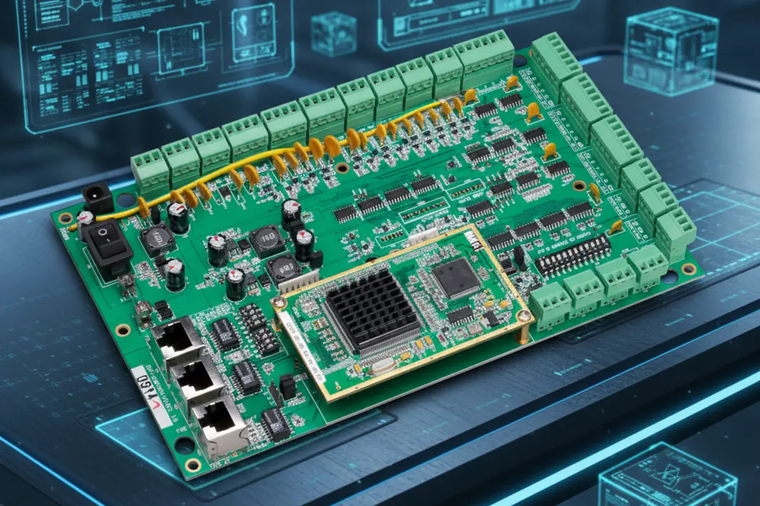
- Motor Drivers and Power Components: Core components include MOSFETs, H-bridge drivers, solid-state relays, etc. High-density integration utilizes the high wiring density and short interconnection paths of HDI boards to simultaneously arrange multiple independent motor drive channels on the same circuit board. Heat dissipation is assisted by thick copper (≥2oz), a heat dissipation via array and a metal substrate.
- Connectors and Actuators: Give priority to industrial-grade connectors that are vibration-resistant, resistant to plugging and unplugging, and equipped with locking mechanisms. The connector should be close to the edge of the board and avoid high-stress areas. If necessary, add dispensing reinforcement or backplane support. Provide isolation drive circuits and freewheeling diodes for solenoid valves, grippers, pneumatic components, etc.
- Solder and Solder Paste Quality: Wave soldering is used for through-hole through-hole devices (THT). Reflow soldering is used for surface mount devices (SMT). Lead-free solders such as SAC305 (compliant with RoHS) are adopted, and the metal composition and flux activity are strictly controlled. For high-reliability applications, high-reliability solder pastes (such as those with low void rates and anti-vibration formulations) can be selected. The solder joint morphology, void rate and wetting Angle were verified through AOI, X-ray and metallographic sections.
Best Practices for High-Performance PCB Design and Manufacturing in Robotics
- Design Rule Check: PCB revisions must undergo a complete Design Rule Check (DRC). Common and easily overlooked failure risks include: short circuit, open circuit, insufficient window opening of the solder mask, and excessive aspect ratio (thick-to-diameter ratio) of the via. Before Gerber export, we enforce the operation of DRC based on the IPC-2221 standard and combine it with DFM rules to avoid manufacturability risks from the design source.
- Heat Management: Under the heat dissipation pads of high-power devices, a via array is adopted to conduct heat to the heat dissipation copper sheet or metal substrate on the back. Physically separate the high-power and sensitive signal areas to avoid thermal coupling and electromagnetic interference. In extreme heat flux density scenarios, metal-based PCBS (MCPCBS) or embedded copper blocks can be selected.
- Material Selection: The selection of base materials for robot PCBS requires a comprehensive consideration of cost, electrical performance, thermal tolerance and mechanical strength. Conventional process robots use FR-4 (high Tg≥170°C); Polyimide (PI) is used for flexible joints/movable parts. The high-frequency radar/communication interface uses the Rogers 4000 series. High-power motor drive boards use aluminum or copper-based MCPCBS.
- BOM and Documentation: A standard design document should include the following four parts, none of which can be missing: complete BOM (Bill of Materials)/production drawings/test plans/version records. Organize the above-mentioned documents into standardized data packages to ensure that customers or factories can directly use them for procurement, material preparation, production and inspection.
- Surface Finishes: ENIG (Chemical nickel gold) is the best choice. Its main advantages include: smooth surface/excellent solderability/corrosion resistance and durability/multiple plug and pull support. Under specific circumstances, hard gold (gold finger), OSP (low-cost and environmentally friendly), or silver/tin plating can also be selected as options.
Prototyping, Gerber Files, and the Robotics PCB Manufacturing Process
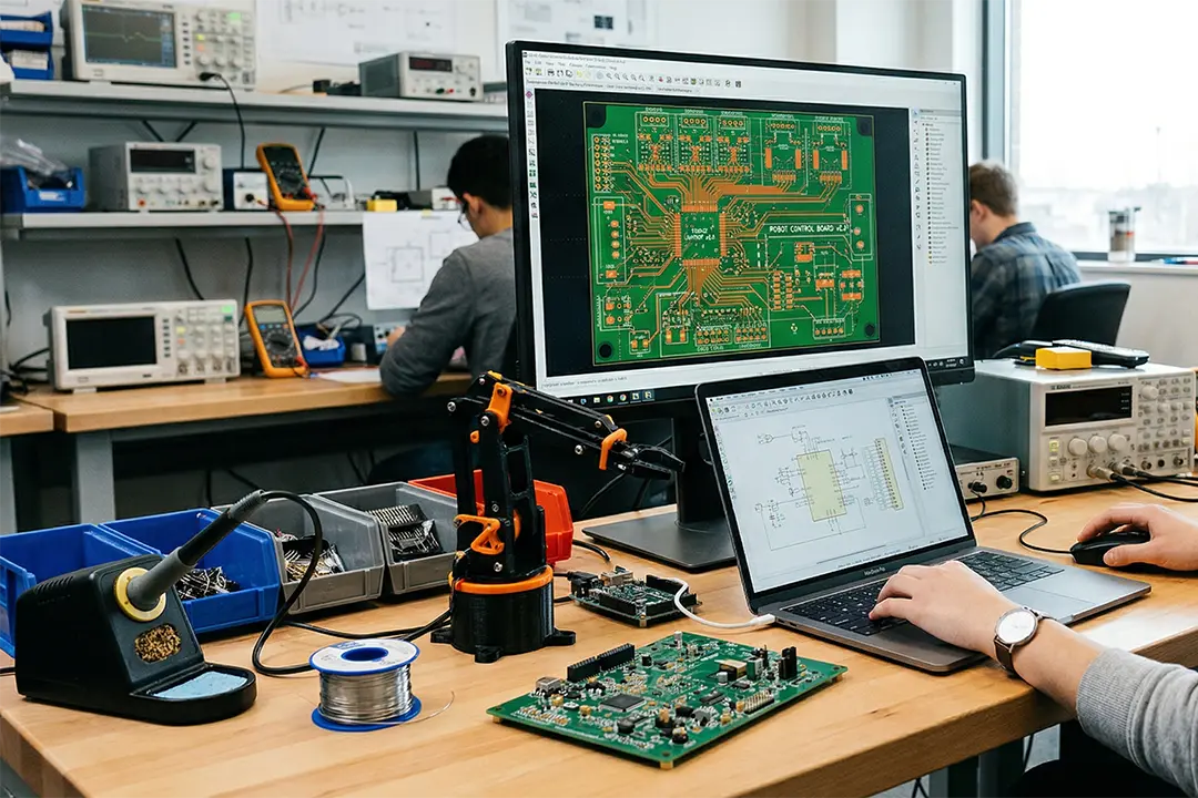
Prototyping
In the robotics PCB design and manufacturing process , early prototyping holds an irreplaceable position. We adopt a phased strategy: first, the initial inspection of the breadboard, then the transition to the PCB prototype, and finally the mixed assembly process. Assist customers in completing the full-process support from breadboard verification to prototype PCB fabrication, and provide professional DFM review and assembly suggestions to lay a solid foundation for subsequent small-batch trial production and large-scale production.
Tips for a high-quality prototyping phase:
- SMT mounting is carried out using solder paste and simple steel mesh.It is recommended to use the process of solder paste printing + hand display + reflow soldering at the prototype stage, and combine it with simple steel mesh (such as laser-cut polyimide template). This approach can simulate the welding quality under mass production conditions.
- Assemble step by step according to the functional modules and test them level by level:
Phase One: Solder the power supply circuit and microcontroller, measure the output voltages of each channel, and confirm that the MCU starts normally and the program is burned.
Phase Two: Add sensors and their signal conditioning circuits to verify the accuracy of data acquisition and noise resistance.
Phase Three: Integrate motor drivers and communication interfaces, and conduct system-level closed-loop testing.
- Conduct small-scale trial production of 3 to 10 pieces: Hand over the PCBA prototype board to those with full-process capabilities of SMT+THT to truly verify whether the design documents meet the requirements of automated production. Expose the assembly difficulties in aspects such as component layout, pad design, and silk-screen marking; Evaluate the repeatability and yield performance of the welding process.
Gerber Files & Design Documents
When preparing the production documents for the robot PCB, please be sure to provide the following standard materials: Gerber files (including copper layer, solder mask layer, silk-screen layer and drilling data), complete bill of materials (BOM), and Pick-and-Place files for the surface mount technology (SMT) machine. All manufacturing documents should be directly exported from the design software, and the format should be carefully checked to ensure compatibility with your PCB supplier.
Checklist for manufacturing process:
- Complete stack-up and layer documentation
- Gerber and drill file verification
- Design rule check (DRC) performed and clean
- BOM with accurate part numbers for every electronic component
- Assembly drawings showing proper orientation for all polarized parts (diodes, capacitors, ICs)
- Clear instructions for any special requirements, such as selective wave soldering or specific surface finishes
Robotics PCB Manufacturing Process
The journey from design to a fully functional robotic circuit board follows these high-precision steps:
- Material handling and preparation: Select the base material based on the application scenarios of the robot: FR-4 (conventional industrial robot) has a good balance between comprehensive performance and cost. The high Tg (≥170°C) version is suitable for temperature circulation environments. Polyimide (flexible or rigid-flex board) is suitable for joint modules or dynamic wiring. The excellent thermal conductivity of metal substrates (MCPCB, aluminum/copper-based) (high-power driver boards) effectively manages the temperature rise of power devices.
- Layer imaging: The photoresist is evenly coated on the surface of the copper foil to form a photosensitive wet film or dry film. UV exposure transfers the circuit pattern to the photoresist through the film or LDI (Laser Direct Imaging). Etching removes the copper layer in the unprotected area to form precise wires, pads and ground layers.
- Drilling: Perform CNC mechanical drilling on all holes that require electrical interconnection or THT insertion, including plated through holes (PTH) and non-plated through holes (NPTH). When drilling micro-blind holes or buried holes, with diameters as small as 75µm, laser drilling is selected. After drilling, plasma or chemical treatment for removing glue residue is carried out.
- Plating and surface finishing: Through chemical copper plating and electroplating processes, a dense copper layer is plated on the hole wall to achieve electrical connection between layers. Select the surface treatment according to the application requirements: ENIG (chemical nickel gold) /HASL (hot air leveling, leaded/lead-free)/hard gold (gold finger) /OSP (organic solder mask).
- Solder mask and silkscreen: Apply LPI (liquid photosensitive) solder mask ink. After exposure and development, expose the solder pads, and cover the remaining areas with an insulating layer to prevent solder bridging, short circuits and oxidation. Print position numbers, polarity marks, version numbers, anti-static labels, etc.
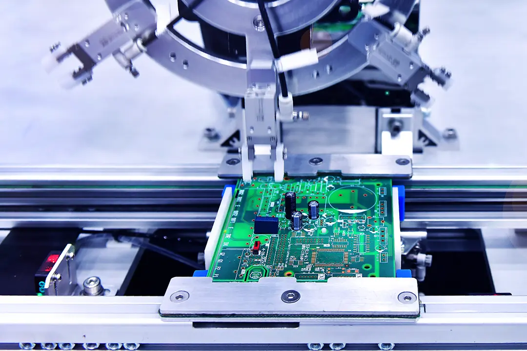
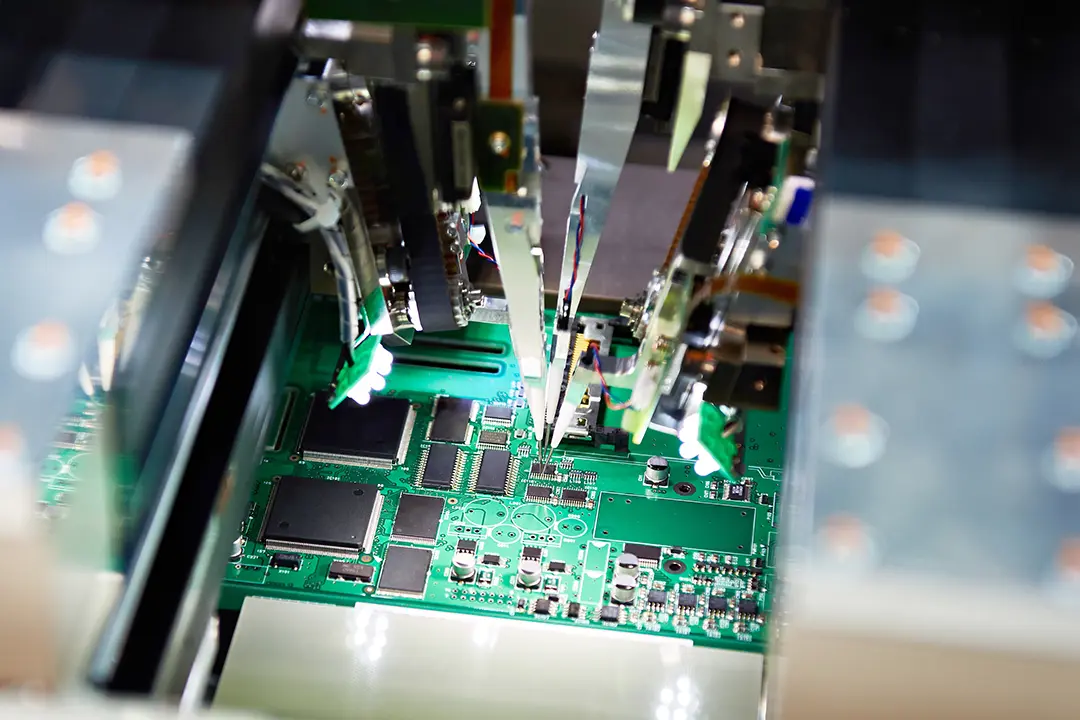
- PCB assembly: SMT mounting uses high-speed Pick-and-Place machines to precisely place surface mount components (resistors, capacitors, ics, connectors, etc.) onto pads and apply solder paste. For devices that cannot be surface mount (such as high-current connectors, transformers, and relays), the THT mounting method is adopted to insert them into the through holes.
- Reflow/wave soldering: After the SMT components are mounted, the circuit board enters the reflow oven and is heated according to the set temperature curve to melt the solder paste and form reliable solder joints. For THT devices, selective wave soldering or conventional wave soldering is adopted to ensure that the solder wave peaks come into contact with the pins and the hole walls, thus completing the soldering. High-density boards often adopt a mixed process of “reflow soldering + selective wave soldering”.
- Testing and inspection: The finished robot PCB must pass the inspection and comply with IPC-6012 and IPC-A-600 standards: AOI (Automatic Optical Inspection)/X-ray Inspection (AXI)/Electrical testing/Flying Probe or ICT/ Functional Testing (FCT)/environmental stress screening.
Quality Testing and Reliability Assurance for Robotics PCB Projects
The standard process forquality testing and inspection of robot PCBS is based on the IPC-6012 and IPC-A-600 standards. We conduct the following multi-level tests and inspections on each robot PCB to ensure that the products meet the strict requirements of the industrial and medical robot fields in terms of electrical, mechanical and environmental adaptability.
Quality assurance process includes:
- Visual inspection: Test all PCBA that have undergone reflow soldering/wave soldering. Detection capability: Bridge between adjacent pins or pads; SMT component misalignment/missing; An open circuit caused by insufficient solder or unformed solder joints.
- Electrical testing: Test and verify that all networks (Nets) have no open circuits or short circuits. Test the integrity, voltage drop and current carrying capacity of the power layer and the stratum; Verify the correct response of the thermal sensitive circuit under simulated working conditions; Small-batch flying probe testing or large-batch ICT fixture testing.
- X-ray inspection: It is applicable to multi-layer boards, high-density interconnect (HDI) boards and PCBA with bottom pins such as QFN, BGA, LGA, CSP, etc., or hidden solder joints. Detect the porosity of the solder balls, cold welding, bridging, and insufficient solder. Continuity of coating on blind/buried hole walls and quality of resin filling holes; Cracks in the inner copper foil of the multi-layer board and lamination voids.
- Thermal cycling and vibration testing: Simulate the temperature changes and mechanical stresses that industrial robots and medical robots face in actual service environments to expose potential failure modes in advance. The test methods adopted include: temperature cycling/random vibration。During and after the test, there was no interruption or permanent drift in the electrical performance. There are no cracks, delamination or component detachment on the appearance.
- Conformation to standards: The physical dimensions, appearance, electrical performance and environmental adaptability of all robot PCBS must simultaneously meet: IPC-6012/IPC-A-600/ customer-specific requirements (such as special impedance, cleanliness, traceability grade)/regulatory requirements (such as RoHS, REACH, UL safety regulations)
Applications of Robotics PCBs: Industrial, Medical, and Automated Robotic Systems
Robotics PCBs are at the core of automation systems in many industries. The following takes industrial robots as an example to demonstrate their key tasks and corresponding PCB design features:
Industrial Robots
- Task: Perform operations such as welding, grasping, assembly and precise positioning on high-speed and highly reliable production lines.
- PCB Design Features:
- Multi-layer board structure: It achieves physical isolation between power circuits and high-speed signals, reducing electromagnetic interference.
- Large-area copper sheet laying: Meets the demand for carrying large currents and optimizes heat distribution.
- Redundant circuit design: Provides fail-safe operation capability to ensure that critical operations are not interrupted.
Medical Robots
- Task: Perform medical procedures with extremely high requirements for accuracy and safety, such as minimally invasive surgery, precise diagnosis and microdrug administration.
- PCB Features:
- Rigid-flex board structure: It achieves highly reliable interconnection within a compact volume, meeting the bending and miniaturization requirements of surgical instruments.
- Gold-plated pads (ENIG/ hard gold) : They offer stable signal connections, are resistant to oxidation, and have low contact resistance, ensuring reliable transmission of weak physiological signals or high-frequency sensing data.
- Patient safety isolation barrier: The electrical isolation area is designed in accordance with the IEC 60601 standard, meeting the creepage distance and electrical clearance requirements to prevent leakage current from causing harm to the patient.
Consumer and Service Robots
- Task: It is used in scenarios such as home automation, vacuum cleaning robots, educational robots and customer-facing interactive robots, emphasizing cost-effectiveness and the reliability of human-machine interaction.
- PCB Design Focus:
- Economical double-layer or four-layer circuit boards: balancing performance and cost, meeting the economic requirements of consumer robots for functional integration and batch production.
- Compact dimensions: Adapted to the design of miniaturized and lightweight complete machines, improving space utilization.
- High-reliability welding and connectors: Utilizing vibration-resistant welding processes (such as reinforced pads and dispensing fixation) and plug-and-pull resistant connectors, it ensures the stability of electrical connections under long-term use, movement or drop impacts.
Automotive and Autonomous Systems
- Task: To achieve navigation and positioning, LiDAR/ radar data processing and autonomous driving control, the circuit board is required to have highly reliable data processing capabilities in extreme environments such as sudden temperature changes, vibration and electromagnetic interference.
- PCB Parameters:
- HDI (High Density Interconnect) technology: Supports high integration and high-speed signal transmission, meeting the requirements of multi-sensor fusion and real-time control.
- High-frequency circuit materials (such as Rogers, PTFE) : Ensure low loss and stable dielectric constant of LiDAR/ radar signals, and improve the accuracy of distance and speed measurement.
- Thermal via array: Effectively conducts the heat of high-power processors (such as FPGA, GPU), maintaining the thermal stability of the system.
- EMI suppression design: By means of a complete ground layer, shielding cover and filter network, it resists interference in the strong electromagnetic environment of vehicles or industries, ensuring the integrity and safety of autonomous driving functions.
Marine and Energy Sector Robots
- Task: When performing operations such as pipeline inspection, seabed monitoring and underwater navigation, one usually encounters extreme environments with high pressure, high humidity, corrosive media and restricted communication.
- PCB Priorities:
- Metal substrate (MCPCB) and conformal coating: The metal substrate (aluminum/copper core) enhances heat dissipation capacity, and in combination with thick conformal coatings (such as poly (p-xylene), acrylic, polyurethane), it provides moisture-proof, salt spray-proof and anti-corrosion protection.
- Mission-critical redundancy design: Implement dual or triple redundancy for core functions such as power supply, communication, and propulsion control to ensure that the system can still operate safely or return autonomously in the event of a single point of failure.
- High-reliability soldering process: Anti-vibration and anti-temperature cycling solder (such as SAC305 or high-reliability tin-lead alloy) is used, and the cavity rate is reduced through strict process control (nitrogen reflux, vacuum soldering) to ensure that the solder joints do not fail under long-term immersion and mechanical shock.
Conclusion: Ensuring Accurate, High-Quality Robotics PCB Projects
Follow this complete guide – from schematic diagrams and design documents to high-quality PCB assembly and rigorous quality testing – and we will help you create a truly successful robot circuit board. Robot PCBS are far more than just simple electrical interconnections: they are the cornerstone for achieving reliable automation, stable performance and breakthrough innovation in applications such as industrial robots, automated medical devices, robots in the Marine and energy fields.
Whether your project is a single-piece prototype or a large-scale production for intelligent robot clusters, the core principles such as robust PCB design and manufacturing, thermal management, high-density layout, compliance with industry standards, and comprehensive testing remain unchanged. We firmly believe that continuous improvement and open communication among engineering teams, suppliers and manufacturers are the keys to achieving long-term success.
Ready to start your robotics PCB journey?
Please put these standards into practice, join hands with a reliable PCB manufacturing and assembly service provider like LHD TECH, use standardized design documents, and always pursue high precision and high reliability. Your next innovation in an automation system, robot or industrial robot – start here, from a robust PCB meticulously crafted by LHD TECH.