
Introduction to AC Capacitor Wiring
When it comes to air conditioning and HVAC systems, although AC capacitors are small, they are key components that ensure the smooth operation of the system motors. Whether you need to replace a failed capacitor, troubleshoot air conditioning issues, or gain a deeper understanding of the wiring details and wire color coding of AC capacitors, LHD TECH has carefully prepared this professional and highly practical guide for you.
Through this guide, LHD TECH will help you
- Clearly distinguish between starting capacitors, operating capacitors and dual capacitors, and understand their specific application scenarios in air conditioning systems.
- Interpret each mainstream AC capacitor wire color and understand why correct wire color coding is crucial for system functionality and safety.
- Learn to read the wiring diagram, accurately identify each terminal of the capacitor, and complete the correct wiring operation.
- Avoid common wiring problems of AC capacitors and master safe capacitor detection methods.
- Master advanced troubleshooting skills: How to deal professionally when the wire color fades or there were incorrect connections in previous maintenance.
Understanding the Purpose of AC Capacitors

How important are the ac capacitors in an air conditioner? In each air conditioning system, the capacitor’s function of storing and discharging electricity helps the motor overcome obstacles, making the entire system run more smoothly. The responsibilities of the capacitor:
- Generate motor starting torque to provide assistance when the fan motor and compressor start.
- Make the current and voltage no longer “synchronized”, and stagger the Angle to make the motor run smoothly and produce less noise.
- The capacitor “balances” during the operation of the motor to improve the energy efficiency of the air conditioner (SEER and SEER2 values).
- Lower energy consumption and prevent damage to the ac by ensuring correct motor operation.
Without functional capacitors—properly wired and matched in microfarads (μF) and voltage rating—fan motors, compressors, and blowers cannot work correctly. In fact, a faulty wiring connection or misuse of a dual-run capacitor is among the top causes of AC failures and expensive repairs in residential and commercial hvac systems.
Different Types of AC Capacitors Used in AC Systems

Today’s HVAC and air conditioning systems use several major types of ac capacitors. Each type is designed with a specific function and correct terminal configuration. Here’s a closer look:
Common Types of AC Capacitors
- Start Capacitor: Provides a short burst of high capacitance to supply motor starting torque. Usually rated at higher μF (often 80–300 μF) and only energized during startup.
- Run Capacitor: Remains in the circuit during normal operation. Rated at a lower but consistent μF (5–60 μF), stabilizes and optimizes running efficiency for the fan motor or compressor motor.
- Dual Capacitor (Dual-Run Capacitor):Combines two capacitors in a single canister, supporting both the fan motor and compressor. Features three terminals (C, FAN, HERM). Dual capacitors are most common in modern split-system and package AC units.
Other less common types used in AC and PCB applications include:
- Electrolytic capacitor: Used for large start loads
- Ceramic capacitors/Safety capacitors (X/Y class): Noise suppression, snubber, or relay protection on PCBs and control boards
- Film capacitors: Used in high-efficiency variable speed drive boards
Where are capacitors used in an AC? Any ac system may have capacitors wired to:
- Hermetically sealed compressor motors.
- Outdoor and indoor fan motors.
- Blower units, especially in variable-speed ac units.
- Water pumps, ignition modules (on advanced HVAC systems)
Terminals of a Capacitor – C, FAN, HERM
Proper ac capacitor wiring requires understanding the specific terminals on the capacitor and each one’s role:
- Common (C): The central hub/return path. Receives power from the line/contactor or PCB and connects internally to both capacitor sections.
- FAN: Connects to the outdoor fan motor run winding.
- HERM (Hermetic): Connects to the compressor run winding.
Some single-phase split-phase motors have four terminals on their starting capacitors, marked with “S”, which stands for Start (Start).
Distinguishing terminals from wire posts is of great significance. Connecting them incorrectly can cause the compressor to overheat or shut down, damaging the system.
Wire Colors and Their Meanings in AC Capacitor Wiring
Choosing the correct wire color is of vital importance. Besides looking at the color, it is also necessary to understand the brand and model, and make a selection by referring to the wiring diagram and equipment manual.
| Function (Terminal) | Typical Wire Color | Destination/Connection | Notes |
| C (Common terminal) | Black / Blue / White | Contactor, Control Board PCB | Main shared return for both motors |
| FAN | Brown / Orange | Fan motor | Brown most common; orange seen in some brands |
| HERM | Yellow / Blue | Compressor run | Yellow is industry standard |
| S (Start) | Red / Black | Start relay or separate cap | Less frequent—check dual cap diagrams |
| Ground | Green | Chassis (not cap terminals) | Safety only; never use for load |
Color Code for AC Capacitor Wiring
Getting the color code for ac capacitor wiring right ensures everything works—and is safe. Reference this comprehensive table for common wire colors you’ll find while wiring ac capacitors:
| Terminal | Color Code | Common Use Examples |
| Common (C) | Black, Blue, White | Main wire from line or PCB, splits to FAN/HERM |
| FAN | Brown, Orange | Outdoor fan motor run winding |
| HERM | Yellow, Blue | Compressor run winding |
| Start (rare) | Red, Black | Motor start {see wiring diagram for type} |
| Ground | Green | Chassis ground; never for active load |
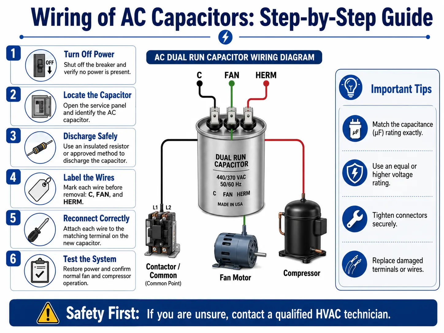
Wiring of AC Capacitors: Step-by-Step Guide
The existing wiring connections and wire colors before you remove anything.
Step-by-Step AC Capacitor Wiring
Label and Document: Use colored tape or marking stickers to clearly mark the terminals (C, FAN, HERM) corresponding to the original capacitor for each wire.
Disconnect Wires: Gently pull each wire out of the terminal with a pair of pointed-nose pliers. Hold the capacitor’s terminals steady with your fingers or another pair of pliers to prevent the terminals from loosening or the capacitor from being damaged.
Match Ratings: Carefully check the rated values (µF and voltage) of the new capacitor. The voltage of the new capacitor must not be lower than the original specification, and the microfarad should match that of the original capacitor (the allowable error is usually within ±6%).
Connect the Common Wire: Connect the common wire (usually black, blue or white) to the C terminal of the new capacitor.
Connect the FAN wire: Connect the brown or orange FAN wire to the FAN terminal. This line supplies power to the condensing fan motor.
Connect the HERM wire: Connect the yellow wire (sometimes blue) to the HERM terminal – this terminal supplies power to the compressor.
Confirm All Connections: Check each wire to make sure it is securely fastened. Loose connections can cause sparking, overheating and even intermittent failures.
Check Everything Twice: Compare the wiring photos with the marking diagrams and recheck whether the wiring of each terminal is correct.
Mount the New Capacitor: Firmly install the new capacitor on the original bracket inside the control box. Good fixation can prevent damage to solder joints or cables caused by vibration.
Restore Power and Test: Close the control box cover, restore the power supply of the air conditioner, and turn it on to run. Check whether the compressor and fan motors have started normally.
Optional: Clamp Meter and Multimeter Testing: Measure the operating current of the fan motor and the compressor with a clamp meter and confirm that it is within the normal range. Use a multimeter with capacitance measurement function to measure the actual capacitance value of the new capacitor and ensure that the deviation from the nominal value does not exceed ±6%.
3 Wire AC Dual Capacitor Wiring
A 3 wire ac dual capacitor setup is the most common in split-system air conditioning units. Here’s how to wire ac dual capacitor wiring for a classic residential AC setup:
- Black/Blue/White (C – Common):
Connects to the common terminal of the compressor and fan, often routed from the contactor or relay.
- Brown (FAN):
Runs between the FAN terminal of the capacitor and the run winding of the condenser fan motor.
- Yellow (HERM):
Runs from the capacitor’s HERM terminal to the compressor’s run terminal.
Wiring Connections: Working with AC Capacitors

Proper Wiring for AC Unit Longevity
- Clean all connectors before installation: Corrosion or oxidation can increase the contact resistance and burn out the terminals directly when heating up
- Never skip the panel ground wire (green):When an internal short circuit occurs, the grounding of the panel wire effectively prevents the risk of electric shock.
- Double-check voltage: Measure each wire with an electricity meter or a clamp meter before touching them. Safety precautions come first.
Specific Wiring Scenarios
Color code for ac in different brands: Trane and Goodman units may use slightly different conventions but still stick to the C/FAN/HERM split.
If replacing only the run or start capacitor: Disconnect only the corresponding wires—FAN or HERM (and S for start-only capacitors)—then re-secure the others to avoid confusion.
For “universal” replacement capacitors: These units come with more terminals. Use only the three labeled C, FAN, HERM, and cap off unused lugs with insulated terminal covers.
Testing after reconnecting: If the unit fails to start or makes humming/buzzing sounds, shut down immediately. Double-check wire color codes and diagram to verify all wires are properly connected.
Testing AC Capacitors: How to Test the Capacitor
Mastering capacitor testing is one of the core skills for diagnosing faults in air conditioning systems.
How to Test AC Capacitors with a Multimeter
Power Off and Discharge: First, turn off the power of the air conditioner, then discharge the capacitor (short-circuit the terminal with a discharge resistor or an insulated screwdriver), and only then can the test begin.
Set Meter to Capacitance (μF): Touch the test leads to the C terminal and the FAN terminal of the capacitor respectively, or the C terminal and the HERM terminal. Read the displayed micrometric value.
Compare to Label:
A reading within ±6% of published value (for run caps) is good.
Start capacitors may be ±10%.
0 μF or “OL” (over limit): Open or failed capacitor.
Check for Common Issues:
Cap bulging, leaking oil, or a burnt smell means immediate replacement.
Physically test the wire at the terminal for looseness.
Look for blackening or melted spots which suggest overheating or past wiring mistakes.
Additional Testing Tips
- Test both capacitor sections in a dual-run model—C–FAN and C–HERM.
- If the current measured by the clamp meter is higher than the normal value, it indicates that the capacitor is damaged or the wiring is incorrect.
- In complex ac units, a failed or miswired cap can also trip control board relays (see “common issues” below).
Common Issues with AC Capacitors
Common AC Capacitor Failures and Causes
| Symptom | Possible Cause & Solution |
| Fan motor fails to run | FAN section of capacitor failed or miswired |
| Compressor doesn’t start | HERM wire not connected, or capacitor bad |
| AC unit hums but won’t cool | Start capacitor provides no torque: replace |
| Both fan and compressor silent | Common wire loose or cap open/fried |
| Cap bloat, leaks, or smells burnt | Overvoltage, overheating, or age: replace |
| Breaker trips when starting AC | Shorted capacitor or incorrect wiring |
| System cycles rapidly (short cycling) | Weak run capacitor or relay contact issue |
Case Study: Wiring an AC Capacitor Incorrectly
There was an inexperienced technician who reversed the HERM terminal (connected to the yellow wire, to the compressor) and the FAN terminal (connected to the brown wire, to the fan) on the capacitor. After he gets the electricity on… What will happen next?
- The fan motor remains silent and the compressor “hums” without starting—sometimes the breaker may trip immediately.
- If the wire posts are connected in reverse, the internal windings of the compressor will be subjected to tremendous pressure, overheat quickly, and the entire air conditioning system will be scrapped.
- If the common wire (the one at terminal C) is not securely connected or connected incorrectly, it may cause both motors will be deprived of proper start/run torque. In severe cases, it could burn out both the air conditioner and the circuit board.
Moral: Carefully check the wiring diagram and the terminal markings on the capacitor, especially before replacing it with a new one. The problems mentioned above can be avoided by self-checking. This is precisely LHD TECH’s guide to ac capacitor wiring: “Look at the wiring diagram, recognize the wire color, and check it again at last.”
Pro Tips for Proper Wiring and Mounting the New Capacitor
- Use Only High-Quality Capacitors: Always select capacitors designed specifically for HVAC systems, rated for your ac unit’s microfarads and voltage (preferably 440VAC, even if the original was 370VAC).
- Replace Spade Connectors if Damaged: If any connector is loose or corroded, cut it off and crimp on a new insulated connector.
- Mount the New Capacitor Securely: Vibration kills capacitors over time—ensure the new capacitor is tightly mounted in its bracket so it doesn’t move or “bounce” during compressor start-up.
- Re-check Wiring: Refer to your photos, wire colors, and diagram one final time after connecting the capacitor.
- Label “Non-Standard” Wires: If your hvac system has non-standard wire color for ac capacitor wiring or if you made any substitutions, label both ends!
- Verify Ground Continuity: Check that the system chassis and capacitor mounting area are solidly grounded, especially in older or rust-prone ac units.
Conclusion: The Ultimate Guide to AC Capacitor Wiring
Mastering of the ac capacitor wiring, understanding wire color codes, and reading reliable circuit diagrams are among the most valuable and safety-related core skills in HVAC system maintenance. Whether you are dealing with dual-operating capacitors in a household air conditioner or troubleshooting commercial compressors on the rooftop, as long as connections to the capacitor terminals according to the correct rules, you can avoid the vast majority of common capacitor faults, protect expensive motors, and ensure that the equipment can cool or heat stably for many years to come.
Today’s air conditioning systems – especially those with PCB control boards, meeting SEER2 energy efficiency standards and adopting advanced PCBA solutions – have extremely high requirements for the precision of terminals and wiring. The correct connection not only concerns safety and surge protection, but also directly affects the warranty compliance of the entire machine.
This ultimate guide from LHD TECH is designed to give you the confidence to handle any on-site task:
No more wrong air conditioning capacitors will be connected. Truly understand how the entire system relies on precise terminal mapping and firm electrical connections, and ensure that every maintenance is done properly.
Remember:
- Always photograph and label before disconnecting ac capacitors
- Check terminal labels, color code for ac, and verify all with the wiring diagram
- Test ac capacitors as part of every troubleshooting and seasonal service
By following this ultimate guide to ac capacitor wiring, you ensure safe, lasting repairs and the comfort your ac unit is designed to deliver.
FAQ: Your AC Capacitor Wiring Questions Answered
Q1: What if I find a red wire, purple wire, or gray wire on my ac capacitor?
A: These colors are not common and are generally used in auxiliary windings, speed regulating taps or certain international models of multi-speed fan motors. We suggest you: Follow this line to find out where it comes from, and then be sure to confirm in the ac capacitor wiring diagram. Never connect it to the C, FAN or HERM terminals casually. Color can help you narrow down the range, but the drawing is the ultimate basis.
Q2: How do I test the capacitor if my multimeter lacks a capacitance function?
A: Do a simple “charge and discharge test” – charge the capacitor with one battery and then short-circuit the two terminals to see if there is any spark. This method can only determine whether the capacitor is completely open-circuited or short-circuited, but cannot measure the capacity attenuation. It is recommended that you borrow or purchase a true RMS multimeter with a μF range for measurement to ensure the safety of the values.
Q3: Can wiring an ac capacitor incorrectly damage my hvac system permanently?
A: Yes. For instance, if the wires of HERM (compressor) and FAN (fan) are connected in reverse, or the common wire (C) is connected to another terminal, or the wiring is done by guessing the color – all these may lead to the direct scrapping of the compressor or fan motor. If it is a relatively new air conditioner, there is also a control board (PCBA) inside. If it is connected wrongly, even the control board may be burned out.
Q4: What is the best way to ensure proper wiring of ac capacitors every time?
A: Always use this checklist:
- Photograph and label all wires before disconnecting
- Reference the wiring diagram for your model
- Match wire color, but prioritize terminal labels (C, FAN, HERM)
- Double-check all connections
- Test the capacitor with a multimeter after wiring
Q5: Why is my new capacitor not fixing the problem?
A: Other causes include a failed relay, broken fan motor, faulty compressor, power supply issues, or incorrect capacitor microfarad value. Always check the entire “chain” in your ac wiring diagram and test each component.
Q6: Can I use a higher voltage rating for my new capacitor?
A: Yes! You can safely use a new capacitor rated at 440VAC even if the old one was 370VAC. Never use a lower rating. Ensure the microfarad value (e.g., 35μF for compressor, 5μF for fan) matches exactly what’s listed for your ac unit.
Q7: How often should I check or replace ac capacitors?
A: Check during every seasonal hvac system tune-up (spring and fall). Replace if you see bulging, leaks, or any drop in microfarads (more than 6% off stated value).
Q8: Is there a universal capacitor that fits all ac units?
A: Dual-run “universal” capacitors exist, but you must match microfarad values and voltage exactly. There is no single cap for all units—always refer to your ac system’s specifications and diagram.