Introduction: The Arduino Nano Pinout Explained
If you’re just getting into electronics or want a small board that doesn’t waste space, the Arduino Nano is a solid go-to. Understanding its pinout is essential—every single pin, from power rails to digital/analog I/O and serial interfaces, is what actually makes the hardware do what you want.
So what’s the big deal about pin mapping? Using each pin the right way separates a project that just works from one that keeps you guessing for hours. In this full walkthrough, we’ll break down the Nano’s pinout in detail—covering power inputs, analog pins, communication buses, good habits, common fixes, and some advanced ideas to really push this board to its limits.
Overview of Arduino & Nano Board
What is Arduino?
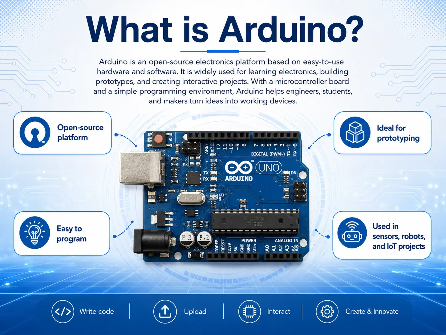
Arduino has made electronics accessible to everyone, from novices to seasoned engineers, thanks to its straightforward microcontroller boards and an easy-to-use integrated development environment. Countless projects—whether in educational settings or early-stage product development—have been built around an Arduino board as the central component, with impressive results.
The Nano Board
The Nano is a miniature board featuring the ATmega328P, with dimensions of just 45 mm by 18 mm. It is specifically designed to fit snugly into breadboards, making prototyping simple and tidy. While it offers nearly the same processing capability as the larger Uno, the Nano is both lighter and more compact, which makes it an excellent choice for designs where space is limited, such as wearables or compact devices.
Main Features:
- Small size, breadboard ready
- Programmed via mini USB
- 30 pins for I/O & power—digital, analog, comms, and more
- Energy-efficient, using the ATmega328P microcontroller
Arduino Nano Pinout Explained: Nano Board, 30 Pins, and Functions

There’s a total of 30 pins on the Nano—each with specific roles in powering, controlling, and communicating with the outside world.
Full Arduino Nano Pinout Table
| Pin # | Pin Name | Function | Details/Usage Example |
| 1 | D1 (TX) | Digital PWM, UART TX | Serial Tx / PWM |
| 2 | D0 (RX) | Digital PWM, UART RX | Serial Rx / PWM |
| 3 | RESET | Reset Pin | Connect to GND to reset |
| 4 | GND | Power Pin | Ground (0V) |
| 5 | D2 | Digital/Interrupt | GPIO / Interrupt 0 |
| 6 | D3 | Digital, PWM, Interrupt | PWM / Interrupt 1 |
| 7 | D4 | Digital | General GPIO |
| 8 | D5 | Digital, PWM | PWM Output |
| 9 | D6 | Digital, PWM | PWM Output |
| 10 | D7 | Digital | General GPIO |
| 11 | D8 | Digital | General GPIO |
| 12 | D9 | Digital, PWM | PWM Output |
| 13 | D10 | Digital, PWM, SPI SS | SPI Slave Select |
| 14 | D11 | Digital, PWM, SPI MOSI | SPI Master Out |
| 15 | D12 | Digital, SPI MISO | SPI Master In |
| 16 | D13 | Digital, PWM, SPI SCK | Built-in LED / CLK / PWM |
| 17 | 3.3V | Power Pin | Regulated 3.3V (up to 50mA) |
| 18 | AREF | Reference Voltage for ADC | External Analog Reference Voltage |
| 19-24 | A0-A5 | Analog Input Pins | Analog input & can be digital I/O |
| 25 | A6 | Analog Input Only | Extra analog input |
| 26 | A7 | Analog Input Only | Extra analog input |
| 27 | 5V | Power Pin | Regulated 5V supply |
| 28 | RESET | Reset Pin | Same as pin 3 |
| 29 | GND | Power Pin | Second Ground |
| 30 | VIN | Power Pin | Input 7-12V (Power Source) |
Nano Board Pin Summary:
- Nano has 8 analog input pins (A0–A7)
- Nano has a total of 14 digital I/O pins (D0–D13), 6 capable of pulse width modulation (PWM)
- All power pins are available for versatile projects
Power Pins: Powering the Arduino Nano – Methods and Best Practices
Power Pins on Arduino Nano Pinout Explained
One of the most important sections is the power pin set. Powering the Arduino Nano correctly not only protects your board, but also safely energizes all components and modules you attach.
Main Power Pins:
- VIN Pin (Power Source): Connect 7–12V DC (battery/adapter). Regulator steps this down to 5V.
- 5V Pin: Regulated 5V out (or power in only if USB not used). Power small peripherals directly.
- 3V Pin: Regulated 3.3V output, up to ~50mA (not for high-draw devices).
- GND Pins: Multiple ground connections for sensors, shields, ICs.
- AREF Pin: For providing a custom analog reference voltage, increasing ADC accuracy in sophisticated sensors.
- RESET Pin: Used for software or hardware reset—important for code upload and debugging.
| Power Pin | Use Case/Note |
| VIN | Use when powering Nano from a battery or DC barrel power jack |
| 5V | For devices that need regulated 5V (draw <= 500mA total) |
| 3.3V | For low-voltage sensors (e.g., BME280, some OLEDs) |
| GND | Necessary common return path in all electronics |
| AREF | Use when your project needs precise analog sensing |
| RESET | Helpful for manual reboot during testing |
Powering the Arduino Nano: Key Scenarios
- USB Only: Most common during development, also powers peripherals (up to ~500mA total).
- VIN/DC Power Jack: Use this in permanent or battery-powered installs. Input range 7–12V (avoid >12V to prevent heat).
- 5V for Regulated Supply: Only if not connecting USB! Useful in multi-board chains fed from a central 5V supply.
Why Power Pin Management Matters
When you’re working on serious electronics projects with the Arduino Nano, managing power usage and planning out your pins really matters. The way you wire up the power pins affects not only what extras you can hook up, but also how long your board lasts without trouble. Say you’re building a weather logger or a portable measuring gadget—figuring out the differences between VIN, 5V, and 3.3V can take a flaky prototype and make it run like a proper, trustworthy tool.
Input and Output: Digital and Analog Pins in Arduino Nano
Digital Pins on the Nano
Arduino Nano pinout gives you 14 digital input/output pins (D0–D13). These can be configured as either input or output in your Arduino code. The digital pins on the Nano handle logic-level signals (0V and 5V). Perfect for toggling LEDs, reading button states, or sending signals to other logic devices.
Pulse Width Modulation (PWM):
- Supported on pins D3, D5, D6, D9, D10, D11.
- Enable precise control of brightness (LEDs), speed (motors), and analog-like outputs.
Using Every Pin on the Arduino Nano
You can use every pin for input and output depending on project needs. Some advanced users use A0–A5 as digital I/O in projects where they need more than 14 digital pins, making the board extremely flexible for prototyping.
Communication Interface of Arduino Nano

One reason the Nano is such a staple in electronics and microcontroller projects is the range of supported communication protocols. This allows the Nano board to interface with displays, sensors, wireless modules, and even other boards.
UART (Serial Communication)
- Pins D0 (RX)and D1 (TX)
- Used to upload code from the Arduino software to the board and for serial monitor communication.
- Can be connected to sensors or modules like GPS and Bluetooth.
I2C (Two-Wire Interface)
- Pins A4 (SDA) and A5 (SCL)
- Supports many sensors/modules (gyroscopes, BME280, OLED, real-time clocks)
- Multiple devices can share these two wires with unique addresses.
SPI (Serial Peripheral Interface)
- Pins D10 (SS), D11 (MOSI), D12 (MISO), D13 (SCK)
- Connect fast devices (SD card readers, Ethernet modules, displays)
- Allows multiple peripherals via separate SS (slave select) lines.
ICSP (In-Circuit Serial Programming) Header
- 6-pin header on the nano board supports programming the ATmega328P directly.
- Also useful for burning bootloaders or recovering “bricked” boards.
| Protocol | Pins | Typical Devices |
| UART | D0 (RX), D1 (TX) | Computer, Bluetooth, GPS |
| I2C | A4 (SDA), A5 (SCL) | LCD, RTC, BME280, OLED Display |
| SPI | D10, D11, D12, D13 | SD card, Ethernet, RF module |
| ICSP | 6-pin ICSP header | Bootloader/Bare ATmega programming |
Arduino Nano vs Arduino Uno and Arduino Mega
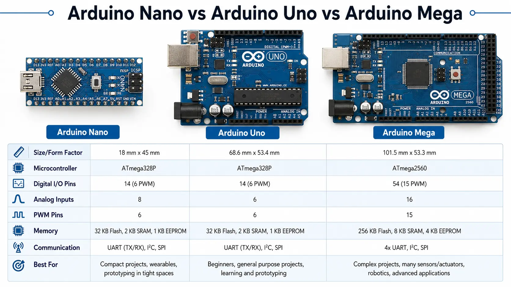
Arduino Nano and Arduino Uno
While the Arduino Uno and Arduino Nano use the same ATmega328P microcontroller, their layouts and capabilities for breadboard projects are quite different.
| Feature | Arduino Nano | Arduino Uno |
| Dimensions | 45 x 18mm | 68.6 x 53.4mm |
| Digital I/O Pins | 14 | 14 |
| Analog Inputs | 8 | 6 |
| USB Interface | Mini USB | Type B USB |
| Breadboard Friendly | Yes | No |
| Power Jack | VIN pin | DC barrel jack |
Nano VS Uno Quick Tips:
- Nano offers more analog pins and breadboard mounting; Uno is best for shield stacking and beginners.
- Choose Nano for compact/embedded installations and when you want to prototype quickly with a breadboard.
Arduino Nano and Arduino Mega
| Feature | Arduino Nano | Arduino Mega |
| Microcontroller | ATmega328P | ATmega2560 |
| Digital I/O Pins | 14 | 54 |
| Analog Inputs | 8 | 16 |
| Power Source | VIN, USB | DC power jack, USB |
| Size | Tiny, breadboard | Large, shield stack |
Nano VS Mega Quick Tips:
- Use Mega only for high I/O count or memory needs (CNC/3D printer projects).
- Nano is ideal for wearable and portable designs.
Programming Arduino Nano and Uploading Arduino Code
Whether you’re experimenting or building full-fledged Arduino projects, uploading code to the Nano is simple:
Steps:
- Connect Nano to PC via mini USB.
- Open Arduino software (IDE).
- Select Board: Arduino Nano, Processor: ATmega328Por ATmega328P (Old Bootloader).
- Choose COM port.
- Load or write your Arduino code and Upload.
Common Pitfalls:
- “Programmer not responding”: Try swapping to Old Bootloader (clones often need this).
- Always check Power Source: USB or 5V, not both!
Troubleshooting and Debugging Arduino Nano
Troubleshooting and debugging Arduino Nano starts with systematic checks:
- Power issues: Confirm voltage at all POWer pins (VIN should be 7-12V, 5V pin should read 5V)
- No output: Test built-in LED (“L” on D13) with blink code
- Peripheral not detected: For I2C, use a scanner sketch; for SPI/UART double-check wiring and pin naming
- Upload problems: Confirm correct board/port settings, or try another computer/USB cable
- PWM not working: Remember only certain pins support pulse width modulation
Common Nano Board Issues
| Symptom | Likely Cause | Fix |
| Board not detected by PC | Bad USB cable, no drivers | Try new cable, USB drivers |
| Can’t upload code | Wrong bootloader/board | Select Old Bootloader/Check select |
| No sensor readings | Wrong pin/wiring | Check Arduino Nano pinout diagram |
| Project resets randomly | Power source unstable | Use stable VIN, avoid USB + VIN mixing |
Arduino Nano Projects: Examples, Ideas, and Best Practice
Example 1: Environmental Station
- Sensors: BME280 (I2C), Analog Soil Probe (A1), Light Sensor (A2)
- Display: OLED Screen (I2C)
- SD Card: For logging (SPI)
Example 2: Wireless Robot Car
- Control: Bluetooth module connected to TX/RX pins
- Motors: H-bridge on PWM pins (D3, D5, D6, D9)
- Sensors: Distance sensor on analog input pins (A0, A1)
- Power Source: 9V battery via VIN power pin
Example 3: Compact Data Logger
- Sensor Inputs: 8 analog sensors connected from A0 to A7
- SD Card Module: Wired to SPI pins (D10–D13)
- Real-Time Clock: I2C (A4/A5)
- Power the Arduino Nano via USB for demo, or use a LiPo battery on VIN pin for field deployment
- Data Handling: Arduino code stores sensor values on SD card in CSV format
Example 4: Mini Game Console
- Controls: Buttons and joystick on digital and analog pins
- Display: OLED or LCD via I2C or SPI
- Buzzer: PWM pin for sound effects
- Power Source: 5V pin from USB or rechargeable battery with voltage regulator
- Arduino Nano supports classic game sketches thanks to ATmega328P RAM and flash memory
Best Practices for Projects Using the Arduino Nano
- Always consult the nano board pinout before wiring, especially when using both digital and analog pins
- For large projects, power the Arduino Nano using VIN + reliable external regulator, not only USB
- Avoid consuming more than 500mA total from 5V pin; split loads if necessary
- Use breadboard for prototyping, then solder headers for sturdy deployments
- Label every connection and document which Arduino pin goes to which external device—future you will thank you!
Conclusion: Why the Arduino Nano Pinout Matters
Getting the Nano’s pinout right can be what turns a messy prototype into a solid, reliable build. Whether you’re using a Nano, an Uno, or even a Mega, knowing your way around its pins—power rails like VIN and 5V, digital I/O, analog inputs, and all the communication interfaces—gives you the flexibility to pull off more complex projects.
Pinout clarity is critical in every area of the electronics world:
- It makes using the Arduino Nano in embedded and wearable projects simple
- It enables fast and safe troubleshooting for beginners and experts alike
- It allows projects using the Arduino Nano to scale with expansion options via I2C, SPI, or merging boards
- It keeps your components safe with correct use of every pin, every power source, and every communication interface
- It unlocks all those tricks: custom reference voltage, multiple power pin setups, battery optimization, creative multiplexing, and quick resets
Nano offers nearly all features of the Uno in a smaller form, making it easy to create, learn, and invent—with the right Arduino Nano pinout, your creativity is the only limit!
Frequently Asked Questions about Arduino Nano Pinout
Q1: What are the main power pins on the Arduino Nano board?
- The main power pins are VIN(for 7–12V input), 5V (regulated output), 3V (regulated for low-power sensors), and GND. Always use only one power source at a time.
Q2: How many analog input pins does the Nano have?
- The Nano has 8 analog pins (A0–A7). A0–A5 can also serve as digital I/O pins; A6/A7 are analog input only.
Q3: Can I use every pin on the Nano for digital I/O?
- Not quite; A6 and A7 are analog input only. All other A0–A5 and D0–D13 can be digital or analog (if supported).
Q4: What is the AREF pin used for?
- The AREF pin lets you set a custom analog reference voltage for high-precision analog measurements.
Q5: How do I power Arduino Nano without USB?
- Simply connect your power source to the VIN pin(7–12V) or to 5V pin (only if USB is disconnected).
Q6: Which communication interface of Arduino Nano should I use for sensors?
- Use I2C for sensors like BME280 or RTC (pins A4/A5), SPI for fast devices (pins D10–D13), and UART for serial (TX/RX on D0/D1).
Q7: Can the Nano board be programmed from another Arduino board?
- You can use the ICSP header or set up Arduino as ISP. The ICSP interface is also used for burning bootloaders onto the ATmega328P.
Q8: Why is my Nano not uploading code?
- Try switching the processor to “ATmega328P (Old Bootloader)” in Arduino software. Check your USB cable and drivers, too.
Q9: What’s main difference between Arduino Uno and Arduino Nano pinout?
- The Nano is breadboard-friendly, includes more analog pins, and is much smaller, but otherwise the digital pin layout largely matches Uno (making it easy to migrate Arduino projects).
Q10: Nano has 30 pins—how do I use them all?
- Plan your pin assignments using the table above and Arduino nano pinout diagram. Remember, some pins serve multiple functions or protocols!