Open up almost any piece of modern electronics — a car’s dashboard computer, a hospital monitor, a drone’s flight controller, and you’ll find the same basic building block. Circuit card assemblies are the heroes of the electronics world. Most people who rely on them every single day couldn’t tell you what’s actually inside one. If you’ve ever wondered what is a circuit card assembly and how it’s different from a plain circuit board, this article is for you. We’re going to walk through the anatomy piece by piece, so the next time you see one, you’ll actually know what you’re looking at.
Breaking Down What Circuit Card Assemblies Actually Are

Let’s start simple. A bare circuit board is the green (mostly green but can also be blue, or black) rigid panel with copper traces etched into it. It is just a substrate: a skeleton with no muscle. Populate that board with components, solder them in, run it through testing, and now it’s a functioning unit. That populated, tested unit is what engineers actually mean when they say circuit card assemblies.
So when someone asks what is a circuit card assembly; in plain English, it’s a circuit board plus everything mounted on it, working together as one complete electronic subsystem. The board by itself can’t do anything. The assembly can.
Layer One: The Substrate
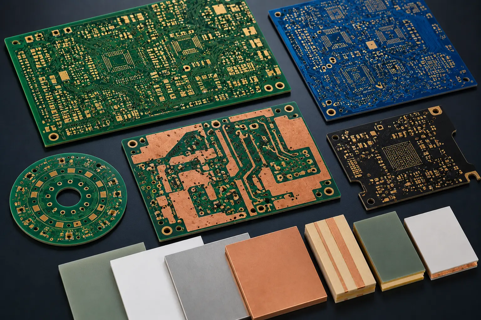
The base material is where circuit card assemblies begin. In most applications, it is FR-4 fiberglass, because it is cheap, stiff, predictable, and does the job. However, FR-4 has its limitations; it cannot work in environments that involve extreme temperatures or high-frequency signals. In such cases, polyimide or ceramic takes over instead.
This layer was never really about holding components in place. Its job is electrical. It keeps signals from bleeding into each other, and keeps doing it for years while the board gets baked, frozen, shaken, and rained on.
Inside that substrate sits the copper. Thin layers of copper foil are etched into precise pathways called traces. It forms the wiring for the whole board.
Simple boards might have two copper layers. On the other hand, the denser designs (think smartphones, avionics) can stack ten, twelve, or more, laminated together like a sandwich.
Layer Two: The Components
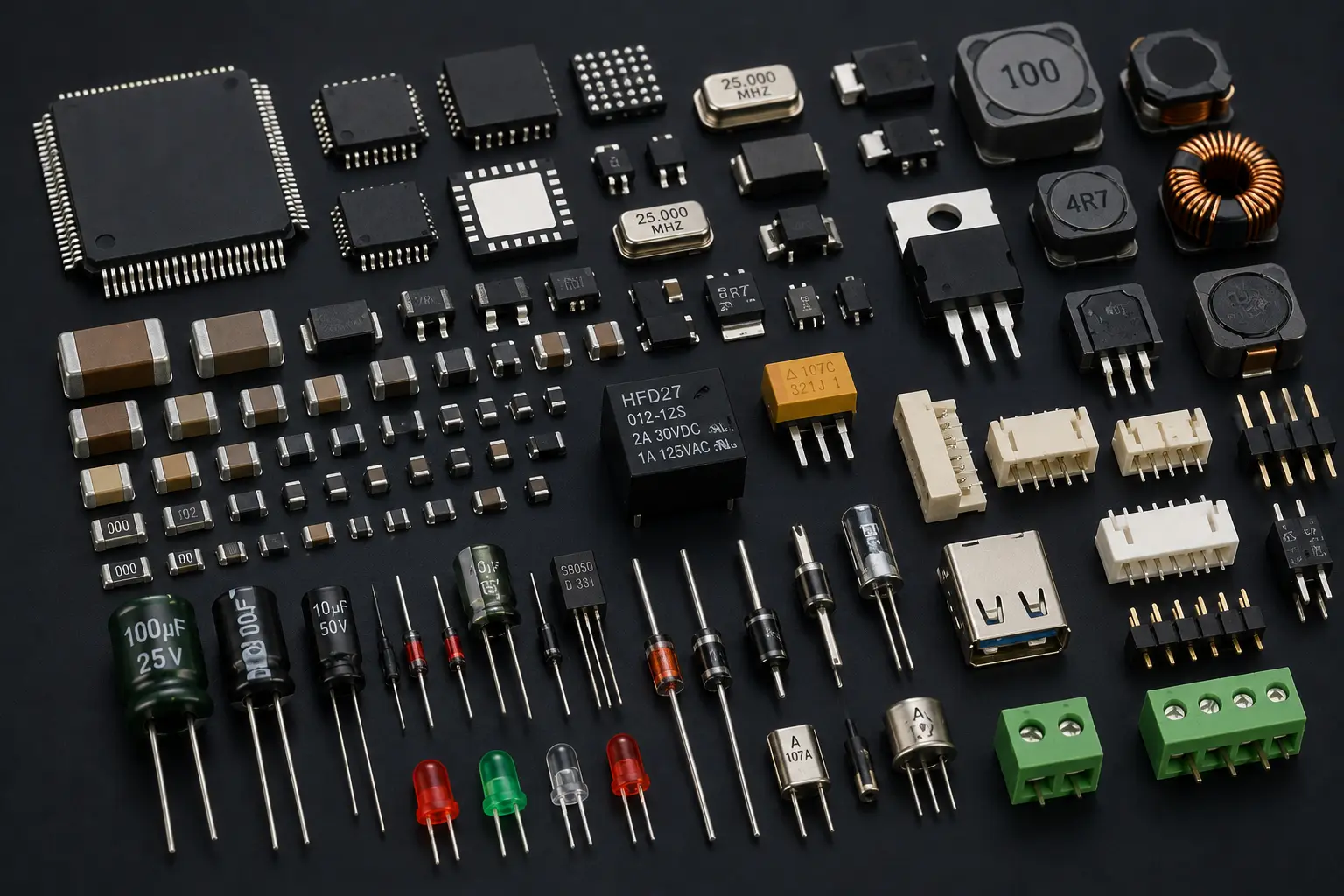
This is where a bare board starts turning into a real circuit card assemb component ecosystem. Every part on there has a job:
- Resistors: control the flow of current, protect sensitive parts downstream
- Capacitors: store and release energy, smooth out power fluctuations
- Inductors: manage changes in current, usually in filtering circuits
- Integrated circuits (ICs): the “brains,” anywhere from simple logic chips to full microprocessors
- Connectors: the electrical and mechanical connection between the board and the rest of the device
- Diodes and transistors: control the direction and switching of current
There are two basic mounting styles used:
- Through-hole parts have leads that pass through drilled holes and get soldered on the back — sturdier, but bulkier.
- Surface-mount parts sit right on pads on the board’s face, which means much denser, smaller designs.
Most modern boards mix both, but rely heavily on surface-mount to keep things compact.
Layer Three: The Solder Joints
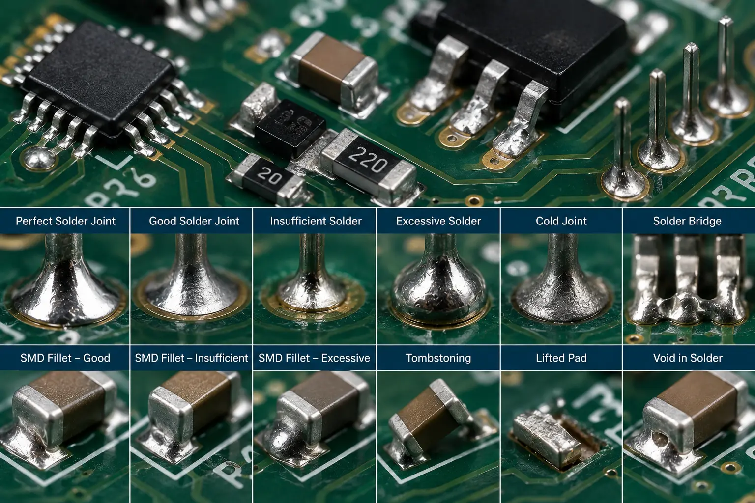
Solder doesn’t get the respect it should. It acts like a glue holding every component to the board. It also creates the electrical connection between components and the circuit board.
At its core, solder is a low-melting-point alloy (most modern electronics use lead-free solder alloys made primarily from tin with small amounts of silver and copper).
It is applied as a simple wire on a workbench. In a factory, its application to the circuit board is through a high-tech, putty-like solder paste printed through a stencil. Either way, the goal is the same: a permanent, reliable bond. Without it, you just have unconnected, loose parts sitting on a piece of plastic.
But when it fails, it fails ugly. You get cold joints, hairline cracks, or microscopic solder bridges that create shorts. None of that is visible to the eye. And that’s exactly why it’s so dangerous. In factories, QA processes include techniques to catch what a human would miss. Building circuit card assemblies that actually survive years comes down to this step more than almost anything else.
Layer Four: Coatings and Protection
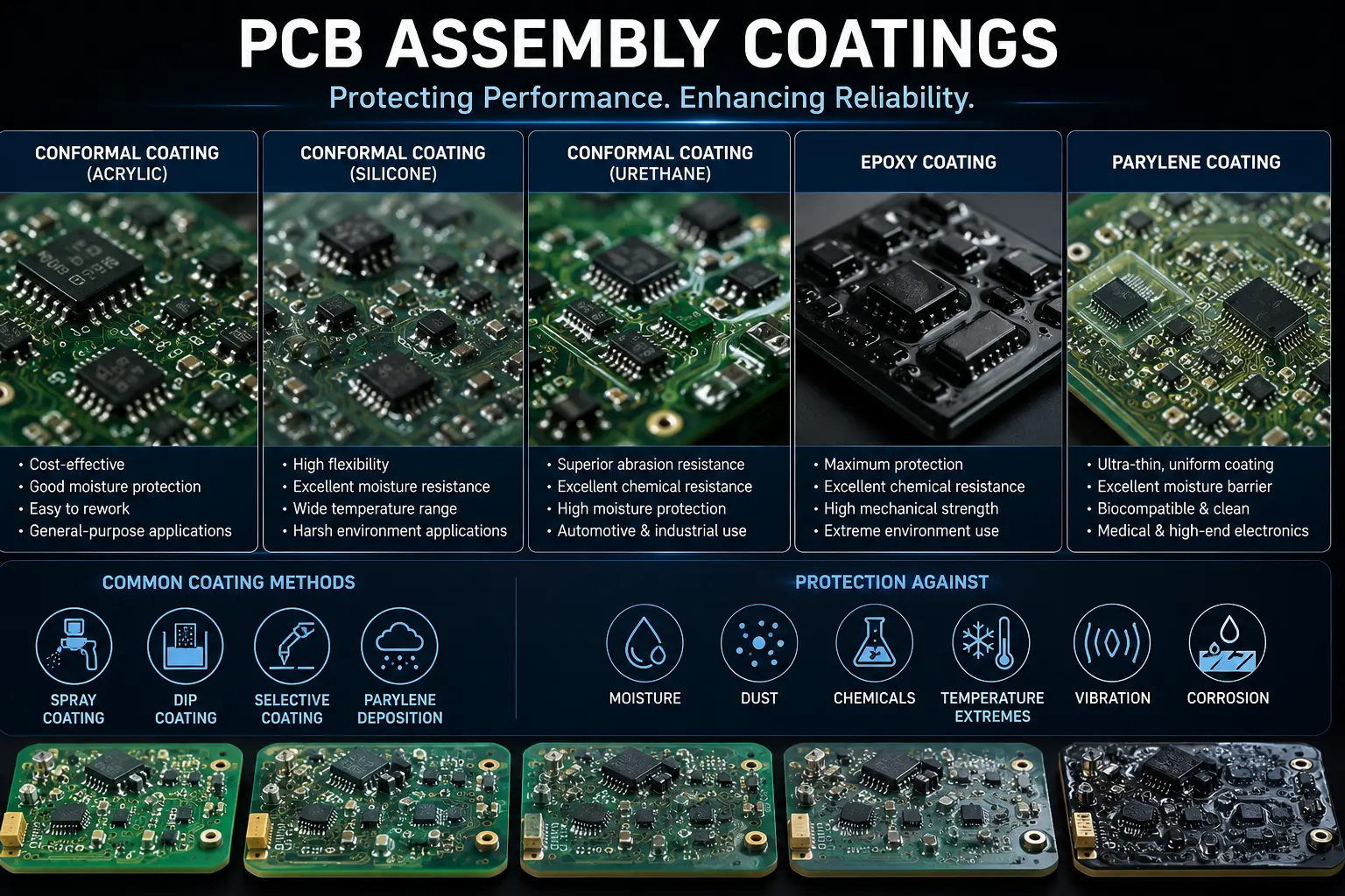
Once a board’s soldered and tested, a lot of manufacturers add one more step: a conformal coating, usually acrylic, silicone, or polyurethane, sprayed over the assembly or applied through a dipping process.
Think of it as a raincoat for the board. It keeps out moisture, dust, salt sprays, chemical splashes, and anything else that quietly eats away the exposed metal over time. Skip it there, and sooner or later, you’ll be looking at a corroded board.
Layer Five: Labeling and Identification
Last step: silkscreen labeling, serial numbers, date codes, sometimes barcodes or QR codes etched right onto the board. In regulated industries like medical and defense, this traceability isn’t optional. It is how a manufacturer proves which batch of materials ended up in which unit, and that matters a lot if a recall or failure investigation ever happens.
Why the Anatomy Matters
A solid circuit card assemb sourcing decision starts with knowing these layers cold. Whether you are sourcing hardware, evaluating a supplier, troubleshooting a failure, knowing where things tend to go wrong gives you a much better sense of what to actually ask about. A cheap assembly and a reliable one can look almost identical from the outside. The difference is buried in these layers, every time.
Putting It All Together
Circuit card assemblies aren’t really objects. They are a sum total of every decision made during their creation. It’s a chain of choices: Did you pick the right substrate for the operating environment? Are the components actually rated for the specs? Were the solder joints verified through inspection, or just assumed to be solid? Did the design account for harsh conditions? If you drop the ball on even one of these calls, the quality of the rest of the build won’t save you. Every layer contributes to the long-term performance of the finished assembly.
So if someone asks what is a circuit card assembly, you won’t just have a textbook answer. You’ll be able to walk them through the substrate, the components, the solder, the coating, and the labeling, all working in concert. That’s the real anatomy behind the boards quietly running the devices we rely on every day. And it’s exactly why so many industries treat the design and manufacturing of circuit card assemblies as a discipline in its own right, not an afterthought.