Even the best of designers can agree that there’s nothing more disappointing than spending months designing the printed circuit board just to discover that it either warps during assembly, overheats in the field or quietly bleeds out signal at high frequencies. In most cases, it’s never the schematics or layout. The culprit is usually the material under it.
The good news? You don’t need to memorise every laminate on the market or become a materials scientist overnight. You simply need to understand which material fits which job.
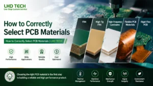
In this guide, we’ll walk through the most common PCB board materials and when to use them.
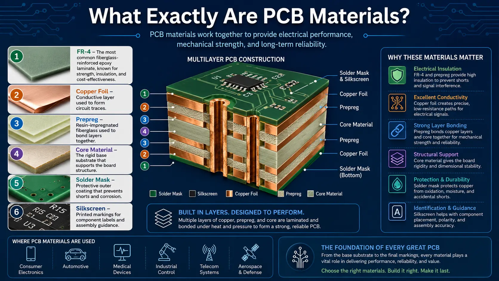
What Exactly Are PCB Materials?
Every printed circuit board starts with a foundation, you could say, and that foundation is the PCB substrate material. It basically gives mechanical support, while still letting electrical connections do their job.
A typical PCB board material is a few elements that work together, and you can spot the pattern when you look at it closely:
- PCB substrate materials that form the structural core
- Copper foil layers used to create electrical circuits
- Insulating resin systems
- PCB soldermask layers that protect circuitry
- Surface finishes for assembly and long-term reliability
All of these components, in combination, decide things like how strong the board is, how stable it stays thermally, how well signals behave, and how durable the whole setup ends up being.
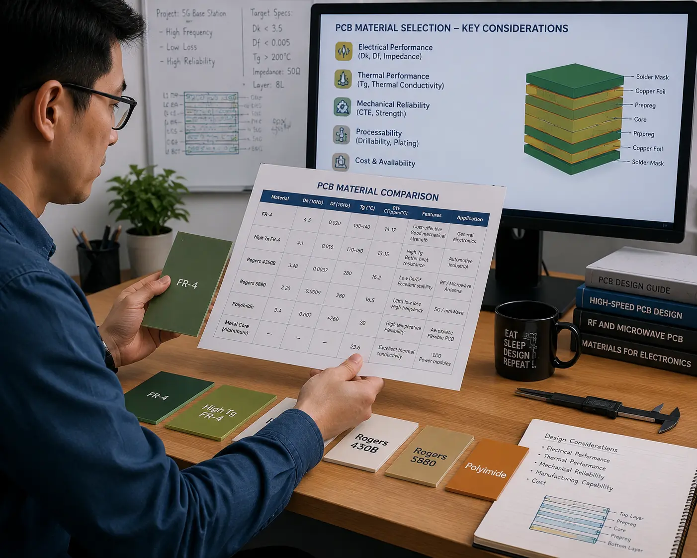
6 Things To Consider When Choosing PCB Material
1. How Fast Are Your Signals Travelling?
Not every circuit pushes electrons to their limits. However, everything will most certainly change once your design starts carrying high-speed digital interfaces or RF signals. At higher frequencies, the PCB substrate material begins influencing signal quality.
2. Can It Handle The Heat?
Electronic components have become smaller, faster, and more powerful. And while that’s a good thing, physics hasn’t become any more forgiving. If the laminate can’t cope with repeated thermal stress, expect warped boards, cracked vias and even delamination between layers.
3. Will the Board Stay Still?
Some PCBs spend their entire lives bolted inside an enclosure, while others get bent, folded, vibrated, or subjected to thousands of thermal cycles. That said, if your design needs to flex repeatedly, a conventional rigid laminate is definitely not the way to go.
4. How Many PCB Layers Will The Design Have?
More layers equals more variables when it comes to PCB layer stackups, and that’s when you’ll start dealing with warpage, uneven expansion, and impedance inconsistencies. The overall PCB layer stackup influences how the board behaves during lamination, drilling, plating, and assembly.
5. Is It Designed For Manufacturability?
Certain PCB board materials demand specialised drilling, longer lamination cycles, tighter process controls, or limited sourcing options while integrating seamlessly into standard PCB manufacturing and PCB assembly (PCBA) workflows. This almost always causes headaches on the shop floor, even if it looks good on CAD.
6. How Do You Plan On Balancing Cost & Reliability?
If your design doesn’t operate at in extreme conditions, a standard FR4 will do. On the other hand, choosing the cheapest option simply because it saves money today can become incredibly expensive if reliability issues come up after production. That’s why it’s always important to find the perfect balance between the two.
Choosing the Right PCB Material
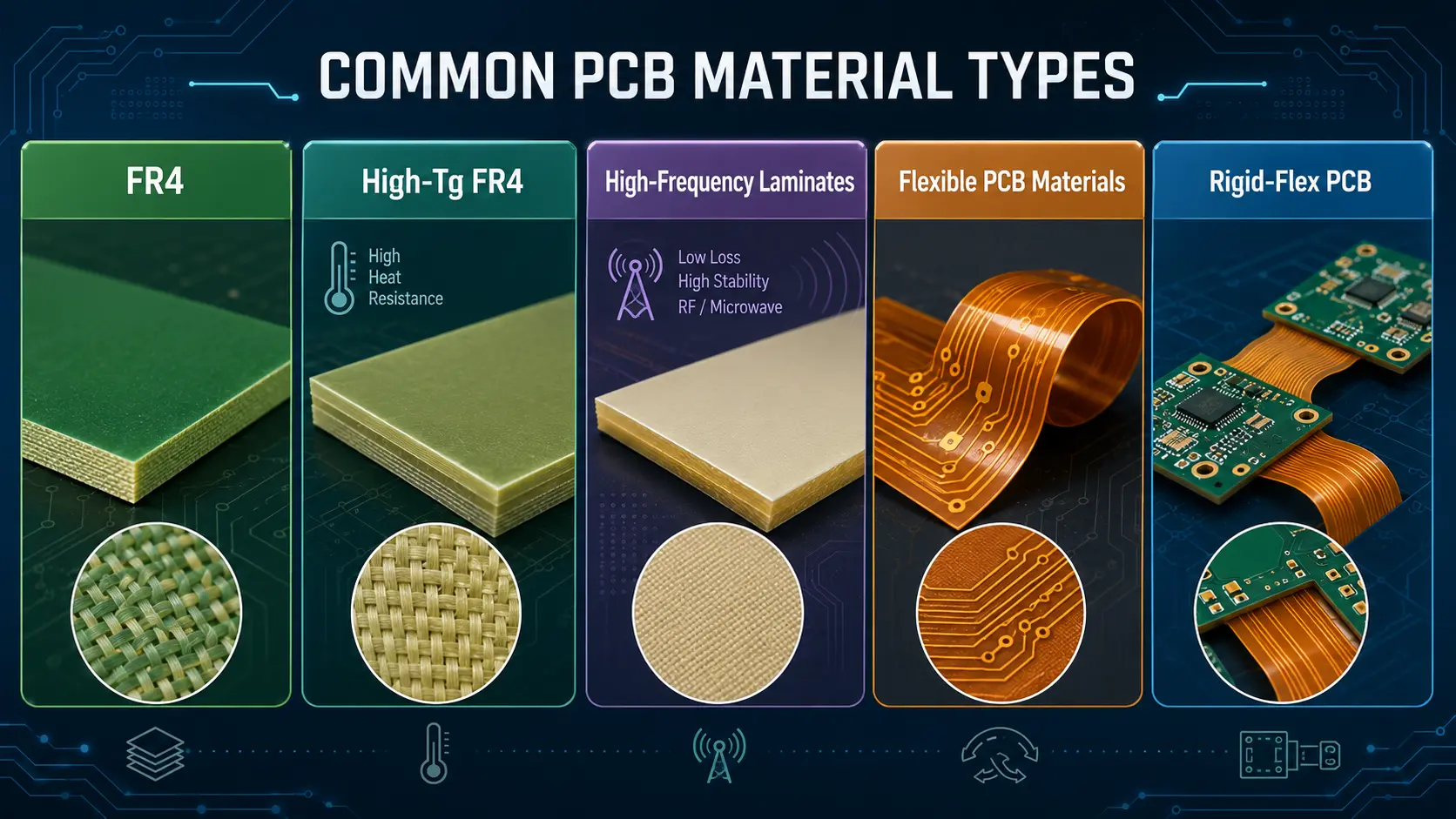
Now that you’ve narrowed down your requirements, it’s time to match them to the right laminate. Here are some of the most common PCB materials and where they work best.
1. FR4
It’s a dependable workhouse that gets the job done. FR4 is one of the most preferred PCB materials of choice, and for good reason. It’s made from woven glass fibre reinforced with epoxy resin, and it offers the perfect balance between electrical insulation, mechanical strength, thermal performance, and affordability. More importantly, manufacturers know how it behaves, designers know what to expect, and procurement teams rarely struggle to source it.
That’s why you’ll find FR4 PCB material in almost every device you can think of.
FR4 is usually the right choice when:
- Your operating temperatures are moderate.
- Signal frequencies aren’t particularly demanding.
- The board remains rigid throughout its life.
- Cost is an important consideration.
- You’re working with standard commercial or industrial electronics.
In other words, if your design isn’t pushing electrical, thermal, or mechanical limits, FR4 is probably all you need. However, if temperatures start to climb, frequencies increase, or reliability requirements become more demanding, you might want to look elsewhere.
2. High-Tg PCB Materials
When you’re working with products that spend years sitting inside engine compartments, factory equipment, power converters, or industrial control cabinets where temperatures regularly climb well beyond what standard FR4 enjoys, you might want to make the move to High-Tg PCBs. But what exactly are they?
“Tg” refers to the laminate’s glass transition temperature, which is that sweet spot where resin stops softening under heat. A higher Tg means the board remains mechanically stable at higher temperatures, minimising the likelihood of warping, delamination, or cracked vias during both manufacturing and long-term operation. This extra thermal stability also makes them a great option for lead-free soldering, where assembly temperatures are higher than traditional soldering.
High-Tg materials are great when working with:
- Automotive electronics
- Power electronics
- Industrial automation
- High-power LED lighting
- Multilayer PCBs
- Heavy copper designs
- Products exposed to repeated thermal cycling
One thing is certain: you’ll definitely pay more than standard FR4. However, it’s money well spent if your board regularly experiences high temperatures.
3. High-Frequency PCB Materials
You’d be surprised at how forgiving electrical signals are, until of course they aren’t. Once your design moves into high-speed digital communication, microwave frequencies, or RF applications, tiny electrical losses that barely mattered before suddenly become major design challenges, from signal reflections and attenuation to timing issues, EM interference and everything in between.
That’s when substrate material becomes an active part of the electrical design, and why you’ll start appreciating high-frequency PCB materials with lower dielectric constant (Dk) and loss tangent (Df) as they preserve signal quality over long trace lengths while minimising energy loss at higher frequencies.
They work best for:
- 5G infrastructure
- RF modules
- Radar systems
- Satellite communications
- High-speed networking equipment
- Aerospace electronics
4. Flexible PCB Materials
Not every product is built around a perfectly flat circuit board. In fact, if you take apart your smartphone, smartwatch, digital camera and other products, you’re guaranteed to find at least one Flexible PCB connecting components inside.
Unlike rigid laminates, flexible circuits use polyimide substrates that allow the board to bend repeatedly without damaging copper traces. They also reduce connector count, save loads of space, minimise weight, improve reliability and simplify assemblies. If your design needs to move, fold, or fit into awkward spaces, Flexible PCBs are the way to go.
They are great when working with:
- Wearable technology
- Smartphones and tablets
- Digital cameras
- Medical devices
- Automotive electronics
- Aerospace systems
- Industrial sensors
- Foldable consumer electronics
5. Rigid-Flex PCB
Sometimes you need rigidity in one area and flexibility in another. That’s exactly what Rigid-flex PCB technology was designed for: to eliminate the need for connecting multiple rigid boards with cables or connectors by integrating both sections in one assembly.
The result? Fewer connectors, better vibration resistance, smaller assemblies, easy installations and reduced assembly times. This makes rigid-flex designs a great choice, attractive for industries where reliability isn’t negotiable.
They are commonly used in:
- Aerospace
- Defence
- Medical devices
- Automotive safety systems
- High-end industrial equipment
While manufacturing costs are generally higher than conventional rigid boards, eliminating multiple connectors, cables, and assembly steps often offsets much of that additional expense.
A Quick Comparison Of Common PCB Materials
| PCB Material | Best For | Heat Resistance | High-Speed Signals | Flexibility | Relative Cost |
| FR4 | General-purpose electronics | Good | Moderate | No | Low |
| High-Tg FR4 | Automotive, industrial, power electronics | Excellent | Moderate | No | Medium |
| High-Frequency Laminates | RF, microwave, 5G, aerospace | Excellent | Excellent | No | High |
| Flexible PCB Materials | Wearables, cameras, medical devices | Good | Good | Yes | Medium-High |
| Rigid-Flex PCB | Compact, high-reliability products | Excellent | Excellent | Partial | High |
The Takeaway?
Choosing PCB materials isn’t the glamorous part of product development, and almost nobody gets excited about laminates or resin systems. But one thing is for sure: if you choose the wrong substrate material, even a carefully engineered board can become an expensive lesson in what not to do.
For many projects, tried and tested FR4 PCB material offers the perfect balance of performance, reliability, and cost. But as operating temperatures rise, signal frequencies increase, or your design demands greater flexibility, materials like High-Tg PCB, high-frequency PCB materials, or Flexible PCB and Rigid-flex PCB solutions become well worth the investment.
Still unsure which material is right for your project? Working with an experienced PCB manufacturing partner can help you balance performance, reliability, and cost before production begins. Let our engineering team review your design and recommend the most suitable material for your use case.
FAQ: PCB Material Selection Guide
Q: What is PCB material?
A: PCB substrate serves as the structural foundation that supports copper circuitry and electronic components. Its insulation properties, mechanical strength, heat resistance, signal transmission quality, and long-term reliability all directly impact the quality and lifespan of the finished circuit board. Material selection is not merely a procedural step; it is a critical factor in determining product reliability.
Q: What are common PCB materials?
A: Common PCB substrate materials can be categorized based on application scenarios: rigid boards primarily utilize FR-4 (epoxy/glass fiber cloth) substrates, with high-Tg FR-4 selected for high-heat-resistance applications, while simple consumer products may use CEM-1 or CEM-3 composite substrates. High-frequency and high-speed applications typically employ polyimide or PTFE/Rogers-series high-frequency laminates; metal-based substrates—available in aluminum-based and copper-based variants—are primarily used for heat-intensive power circuits; additionally, there are flexible copper-clad laminate materials suitable for applications involving dynamic bending.
Q: Which material is most commonly used for PCB boards?
A: FR-4 is currently the most widely used PCB substrate material. Its widespread adoption stems from an optimal balance of cost, mechanical strength, insulation properties, and manufacturability—sufficient to meet the design and manufacturing requirements of the vast majority of standard PCBs.
Q: What is the best material for PCB?
A: There is no such thing as a “universal” PCB substrate. The appropriate material must be selected based on the specific application scenario, operating temperature, signal rate and frequency, power level, structural design, and budget.
Q: How to choose PCB material?
A: Selecting the right PCB substrate requires looking beyond a single metric. You must evaluate a range of parameters—including thermal properties (such as Tg), electrical performance, thermal conductivity, and structural characteristics—and finally consider the specific product type (whether it is a rigid, flexible, high-frequency, or power board), as the material selection criteria differ significantly for each.
Q: What are the different types of PCB materials?
A: PCB substrates can be broadly categorized based on their structure and properties into rigid boards, flexible boards, rigid-flex boards, high-frequency boards, metal-based boards, and high-temperature resistant boards. Each type excels in specific areas—such as high-speed signal transmission, high-power heat dissipation, bending reliability, or tolerance of high-temperature environments.
Q: When should I choose High-Tg FR-4 instead of standard FR-4?
A: When is High-Tg FR-4 recommended? High-Tg FR-4 is the safer choice if your PCB operates at consistently high temperatures, undergoes lead-free soldering or multiple reflow cycles, or features a high-density multilayer structure requiring superior dimensional stability.
Q: When should I use high-frequency PCB materials?
A: When should high-frequency materials—such as PTFE, Rogers, and other low-loss laminates—be used? They are essential for applications involving high RF, microwave, or high-speed digital signals, as well as products like antennas, radar systems, 5G equipment, and communication modules. In these contexts, the stability of the material’s dielectric constant (Dk) and the level of its dissipation factor (Df) directly determine signal stability. For high-frequency applications, stability and low loss are critical performance metrics.
Q: Is PCB made of fiberglass, plastic, or copper?
A: PCB substrates are typically multi-component composite material systems. Taking the most common type, FR-4, as an example: its structure consists of an insulating dielectric layer formed by combining a reinforcing material (glass fiber cloth) with a matrix resin (epoxy resin), clad with conductive copper foil layers on one or both sides, and then laminated under high temperature and pressure to produce a copper-clad laminate (CCL). Circuit patterns are subsequently formed on the copper foil via an etching process to establish electrical interconnections.
In addition to the FR-4 series, other functional substrates are frequently used in engineering practice, including polyimide (PI) substrates, ceramic-filled substrates, metal-based substrates (aluminum-based or copper-based), and PTFE-based substrates.
Q: How does PCB thickness affect material selection?
A: How is board thickness determined? It depends on factors such as mechanical strength, impedance matching, connector stability, heat dissipation capabilities, and manufacturing yield stability. While the standard thickness is typically 1.6 mm, adjustments are made based on specific product requirements: boards for compact, lightweight devices are made thinner; high-power boards are thickened to handle high currents and dissipate heat; and certain structural designs necessitate non-standard thicknesses.