Key Takeaways
- Printed circuit boards (PCBs) are available in many variants: single-layer, double-sided, multilayer, rigid, flexible, rigid flex, HDI, metal core, ceramic and other board types. Every variant is built to match specific electronic parts, circuit designs and application sector demands.
- Selecting the right PCB type makes a real difference to product cost and performance. It also determines reliability, production feasibility, thermal dissipation and overall footprint of your end-product.
- FR-4 is still the mainstream base material for PCBs. Meanwhile, polyimide, aluminium, PTFE and ceramic substrates are widely adopted for high-frequency, high-heat and flexible electronic applications.
- HDI PCBs (high-density interconnect) and advanced multilayer design together with sophisticated multilayer layouts enable higher component packing density, which supports miniaturisation needs for consumer electronics as well as aerospace equipment.
Work with an experienced PCB manufacturer that offers custom PCB solutions, advanced fabrication capabilities and assembly know how, so you can source circuit boards well matched to your project requirements.
Introduction to Printed Circuit Boards
What is a Printed Circuit Board?
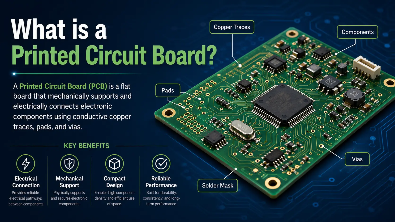
A printed circuit board (PCB) is a flat panel built on non-conductive substrate materials — most commonly FR-4 epoxy or polyimide — bonded with thin conductive copper foils. It holds electronic components in place, delivers orderly circuit trace routing, and delivers mechanical strength plus environmental stability for nearly all electronic devices.
Why are there so many PCB types?
As electronics evolve, PCB specification needs keep changing too. You can find simple single-layer PCBs inside regular calculators, while aerospace satellites rely on high-frequency ceramic PCBs. Engineers leverage variations in layer quantity, base substrate materials and manufacturing processes to satisfy distinct circuit design objectives.
The Evolution of PCB Technology
The invention of the printed circuit board completely transformed circuit assembly, quickly doing away with traditional point to point wiring. Decades of progress in PCB design methodologies, high-performance substrate materials and sophisticated manufacturing techniques have driven the development of smaller, more dependable electronics. These products serve consumer, industrial, automotive, medical and aerospace fields alike. Understanding various PCB categories and their ideal application scenarios lays the groundwork for solid PCB layout and product development.
Multi-Faceted PCB Classification
Printed circuit boards are best classified by the following characteristics:
- Layer count (single-layer, double-sided, multilayer PCBs)
- Mechanical form (rigid, flexible, rigid-flex PCBs)
- PCB material (FR-4, polyimide, PTFE, aluminum, ceramic)
- Fabrication and process features (via types, HDI, copper thickness, surface finish)
- Application field (high-frequency, power, medical, consumer electronics, automotive, aerospace PCB needs)
Let’s explore the main types and key differences.
Classification by Layer Count
Single-Layer PCB (Single Sided)
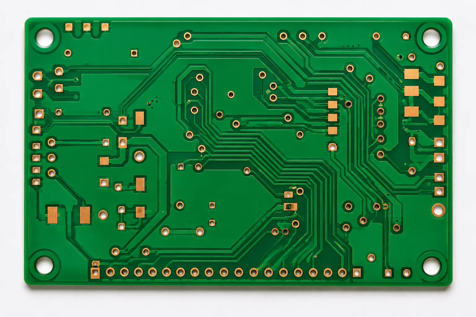
A single-layer PCB uses 1 layer of copper on a rigid or flex substrate material. Traces are routed only on one side, mini cost but limiting complexity.
- Best for: Simple consumer electronics, calculators, basic lighting, low-frequency and low-power circuits.
- Board Materials: FR-4, CEM-1.
- Example: A low-cost kitchen timer will often use a single PCB to host just a microcontroller, buzzer, display, and switches.
Double-Sided PCB
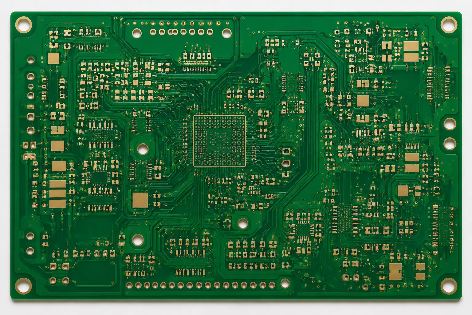
A double-sided PCB (or double layer) features conductive copper traces on both its top and bottom surfaces. Through-hole vias link these two sides together, allowing for greater component packing density and more intricate circuit routing.
- Common PCB Types: Industrial controllers, power supplies, small motor drivers.
- Fabrication: Enables improved routing and smarter layout for medium-complexity circuits.
- Tip: Opt for double-sided for cost-effective PCB fabrication where component mounting on both sides reduces board size.
Multilayer PCBs
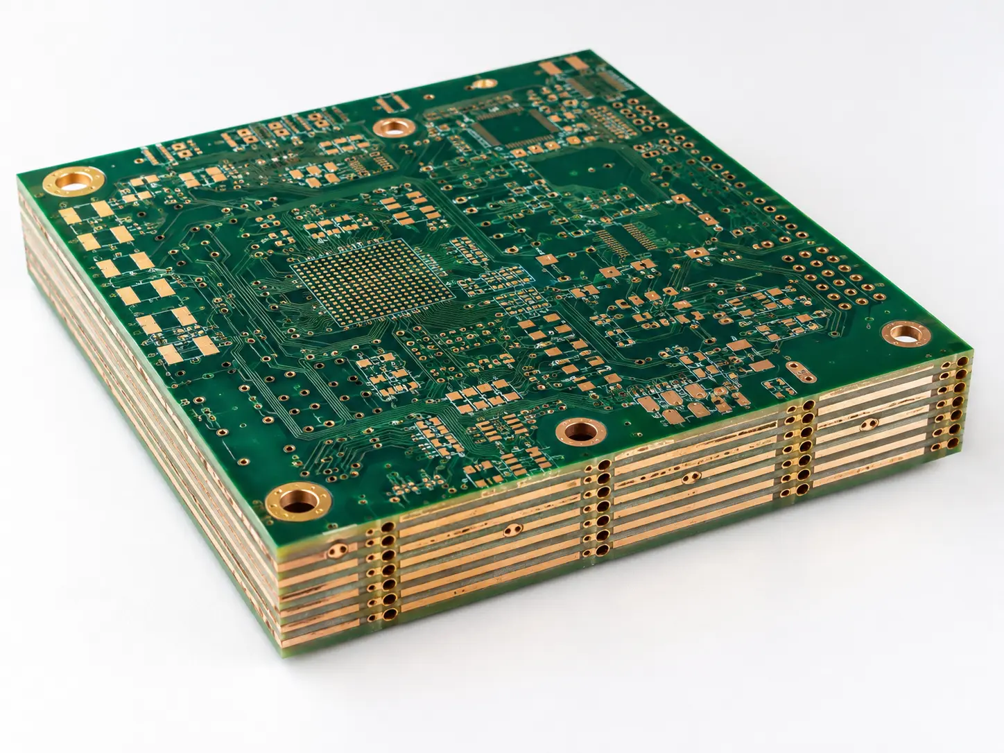
Multilayer PCBs (typically 4 to 20+ layers) They are constructed by stacking alternating copper circuit layers and insulating epoxy or polyimide dielectrics. Inner layers are reserved for power distribution, ground planes and high-frequency signals, whereas outer layers accommodate densely-populated electronic components.
- Best for: High-speed servers, routers, medical imaging, and aerospace guidance.
- Substrate Material: FR-4, high Tg FR-4, polyimide, PTFE.
- Benefit: Multi layer design allows ultra-compact, shielded, high-performance circuits with minimum interference.
- Tip: HDI and multi layer PCB boards are essential for miniaturized, multi-function electronics in IoT, telecom, and avionics.
Classification by Mechanical Form
Rigid PCBs
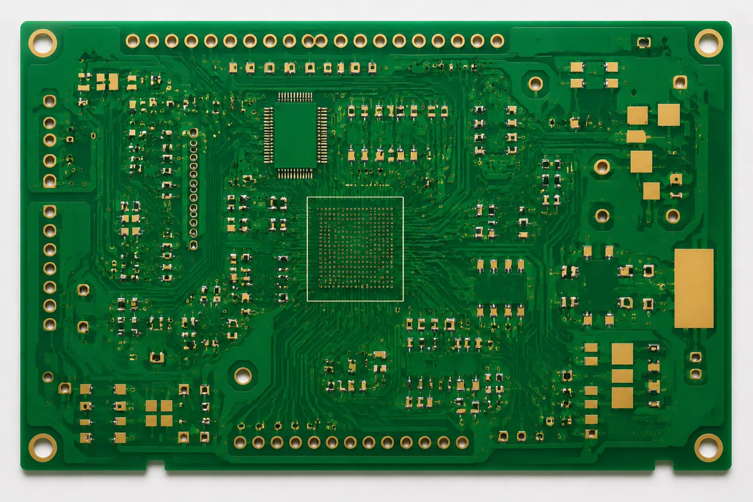
Rigid PCBs (rigid boards) represent the conventional baseline for most electronic devices. Built using non-bendable FR 4 or CEM laminate materials, these boards offer sturdy mechanical backing for bulky components while maintaining stable circuit connections.
- Used for: Consumer electronics, laptops, industrial controls, automotive power modules.
- Design and Performance: Allow precise, stable component mounting and automated PCB assembly.
- Limitation: Can’t conform to curved or moving surfaces.
Flexible PCBs (Flex PCBs)
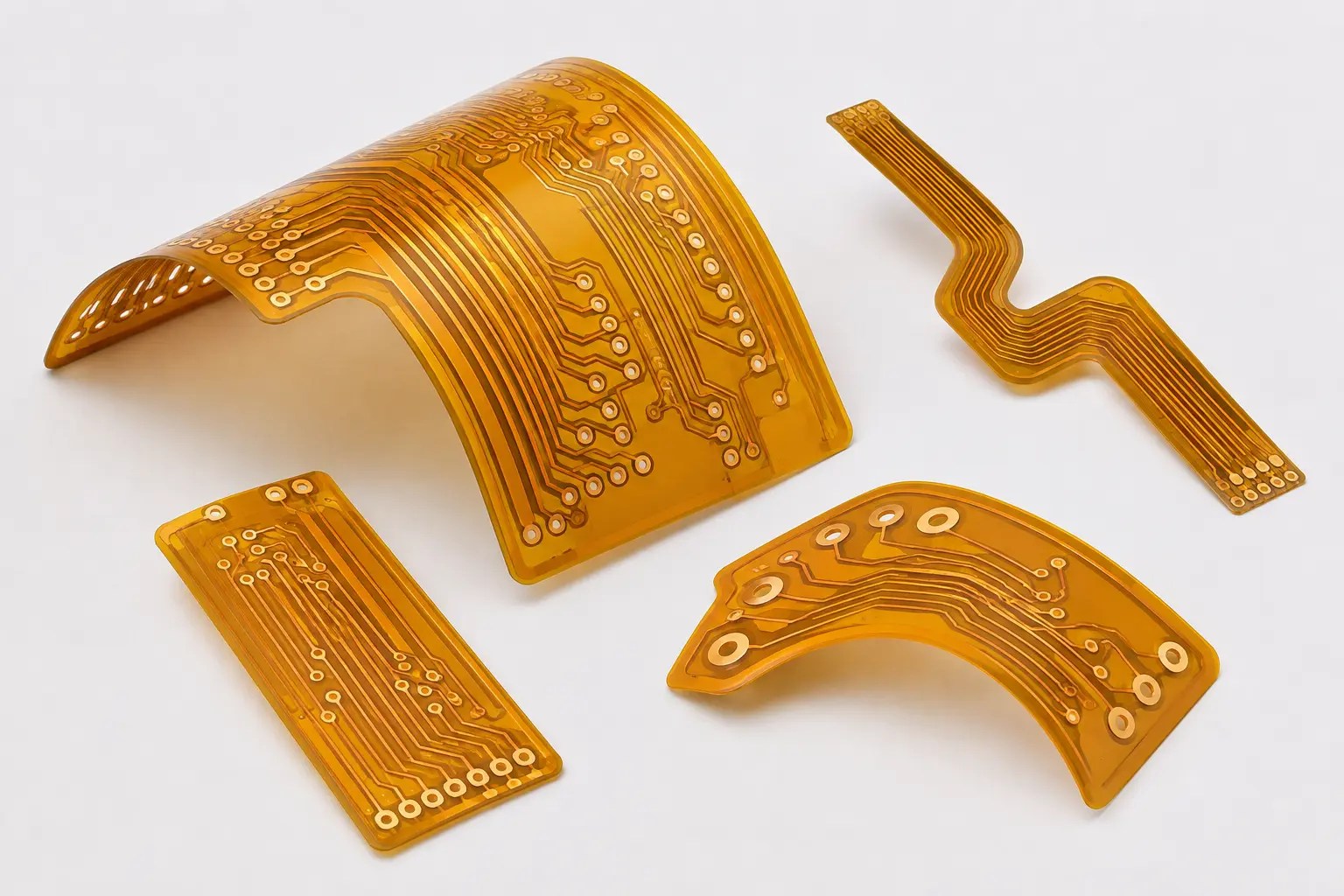
Flexible PCBs use polyimide or PET as the main substrate material, allowing the circuit to bend or fold. This provides new opportunities for creative PCB layout and unique shape constraints.
- Electronic Components: Sensors, camera modules, foldable displays, medical probes.
- High Performance: Support lightweight, shock-resistant, and space-constrained products.
- Engineering Tip: Maintain wider trace widths in flexible sections to reduce fatigue during bending.
Rigid-Flex PCBs
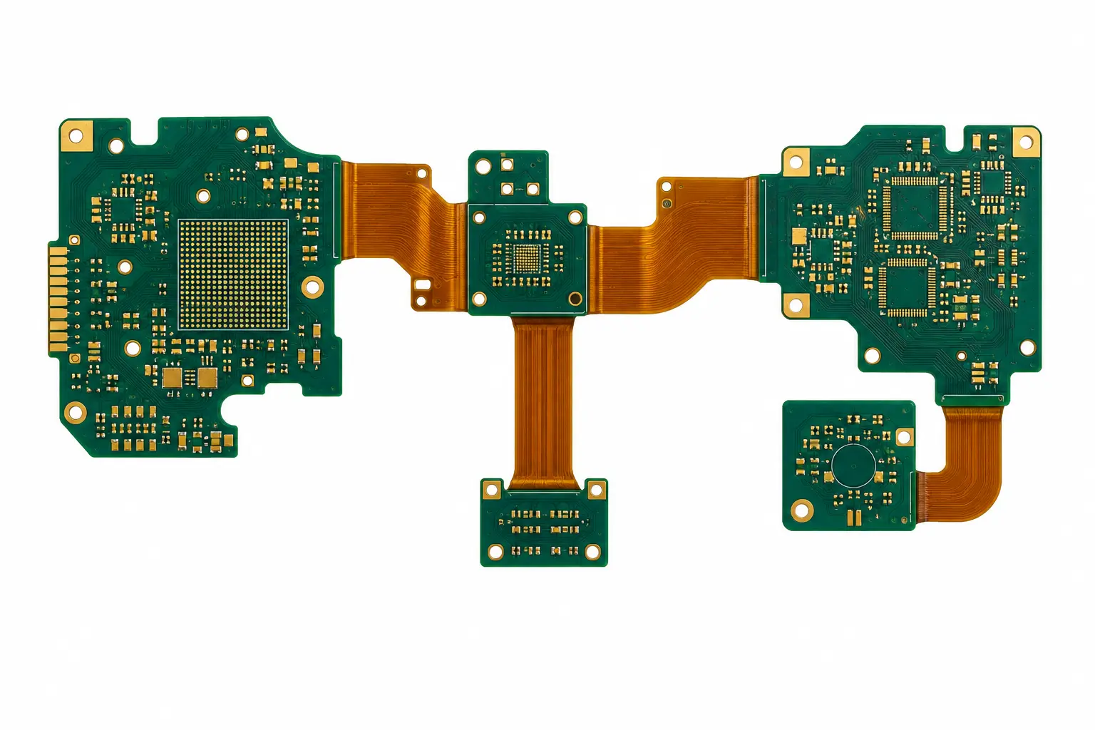
Rigid-flex PCBs combine rigid sections (for dense electronic components and connectors) with flexible sections. They’re the go-to circuit board for aerospace, medical, military, and advanced consumer electronics requiring both packaging flexibility and PCB assembly reliability.
- Example: Aerospace avionics allocate rigid sections for processors and flexible sections for harness elimination, reducing failure points.
- Tip: Rigid and flexible PCBs increase assembly reliability and drastically reduce weight—especially where vibration or repeated motion is expected.
Classification by Board Materials
FR-4: The Common PCB Material
FR-4 (fiberglass-reinforced epoxy laminate) and it takes up around 80 percent of the worldwide standard PCB market. Thanks to its good mechanical strength, flame retardant property, cost-competitive price and solid electrical insulation performance, it serves as the go to substrate for countless electronic applications.
- Pros: Low cost, high insulation, reliable for up to 6-8 layer count, excellent for both analog and digital circuits.
- Limitation: Not ideal for frequencies above a few GHz, nor extreme heat or flexing.
- Tip: Most prototypes, consumer electronics, and industrial controls, they all use FR-4 for initial runs on supply chain robustness.
Polyimide
Polyimide is the go to substrate for flexible PCBs, as well as high-performance circuits that must withstand extreme temperatures, such as those used in aerospace, automotive and military hardware.
- Benefits: Superior flexural strength, high glass transition temperature, excellent chemical resistance.
- Example: Medical implantable devices and flexible interconnects in satellites rely on polyimide for longevity and ruggedness.
Metal Core PCBs
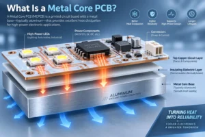
Metal core PCBs (MCPCB; often aluminum or copper core) They outperform conventional glass-epoxy boards when it comes to isolating circuits and drawing heat away from power LEDs and high-current traces.
- Used for: LED lighting panels, high-wattage power converters, automotive ECUs.
- Tip: Choose metal core for cost-effective, robust LED lighting PCBs with minimal thermal management complexity.
Ceramic, PTFE, Rogers
- High-Frequency & High-Performance Applications: Boards built on ceramic or PTFE (Teflon) substrates deliver ultra-low signal loss alongside stable high-frequency, high-fidelity signal transmission. Specialty laminate materials such as Rogers and Arlon fit this category perfectly, and perform exceptionally well in 5G hardware, radar systems and satellite payload equipment.
- Limitation: Higher cost and more challenging fabrication require partnership with a specialized PCB manufacturing partner.
Classification by Process & Features
HDI PCBs (High-Density Interconnect)
HDI PCBs stand as a state-of-the-art advancement within printed circuit board technology, helping electronics grow smaller, more powerful and more robust. Utilizing microvias, blind vias, buried vias and ultra-fine copper traces, HDI boards achieve higher component density and handle more complex routing compared with conventional PCBs. This sophisticated manufacturing method makes it possible for modern day devices including smartphones, fitness wearables, IoT sensors and aerospace navigation modules to pack extensive functions into minimal physical space.
Key Features of HDI PCBs:
- Microvias: Miniature vias produced through laser drilling. They link adjacent board layers while taking up very little board area.
- High Layer Count: Sophisticated multilayer PCB stack-ups are widely used for high-end electronics, some featuring over eight HDI layers.
- Enhanced Routing Flexibility: Compatible with BGA (Ball Grid Array), plus fine-pitch QFN and LGA component packages that cannot be implemented on regular PCBs.
- Improved Signal Integrity: Shorter, more direct trace paths cut down signal loss and electromagnetic interference (EMI). This proves vital for high-speed and high-frequency digital circuits.
- Applications: Commonly adopted for medical-imaging hardware, aerospace guidance control systems, premium consumer electronics such as smartphones and tablets, as well as automotive radar units.
Via Structures and Advanced Routing
A vital aspect of modern multilayer PCB board types is the way connections—or vias—are structured. Vias are the “vertical traces” of the PCB, enabling signals to pass between different layers in a multilayer stackup.
Types of Vias:
- Through-Hole Vias: Simple holes connecting all board layers; robust but consume valuable board space.
- Blind Vias: Vias that connect outer layers to one or more inner layers without passing through the board, increasing usable PCB real estate.
- Buried Vias: Only connect inner layers and remain invisible from the exterior—a hallmark of advanced HDI and aerospace boards.
- Microvias: Ultra-small vias in HDI PCBs, ideal for tight routing between high-pin-count ICs or in miniaturized IoT designs.
Design Tip: Make sure you verify your PCB manufacturer’s specs for minimum via sizes, copper plating thickness and drill tolerances. This is especially critical when working with HDI boards and intricate multilayer layouts.
Surface Finish and Soldering
A circuit board’s surface finish affects its solderability, signal integrity and storage lifespan. Common surface finish choices are HASL (Hot Air Solder Leveling), ENIG (Electroless Nickel Immersion Gold), OSP (Organic Solderability Preservative), immersion silver and immersion tin..
- ENIG widely preferred for HDI PCBs and BGA component mounting. It is also the go-to finish for aerospace and medical projects that demand high-performance, corrosion-resistant surface treatment.
- HASL and OSP are heavier use on standard FR-4 boards and one-off PCB prototype builds.
- Immersion Silver/Tin making them well-suited for fine-pitch parts and high-frequency use-cases.
If your PCB assembly workflow adopts lead-free solder, you need to select RoHS-compliant surface finishes and double-check their compatibility with your selected components.
Choosing the Right PCB Type: A Buyer & Engineer’s Guide
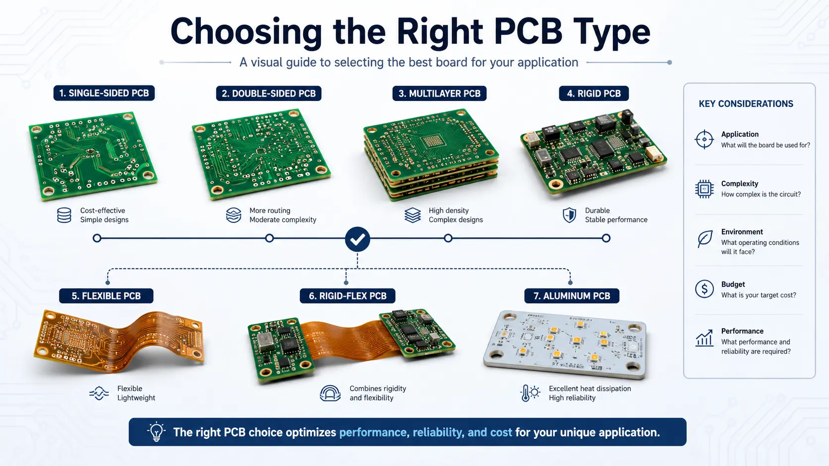
Choosing the right PCB type is foundational for a successful, durable electronic device.
Step-by-step Selection Process
Define Your Requirements:
- Will your circuit board face vibration (automotive, aerospace) or be flexed (wearable, medical)?
- What layer count and routing complexity does your PCB design need?
- Is high-frequency signal integrity (5G, RF, WiFi) critical?
Evaluate PCB Materials:
- Default to FR-4 for most consumer and industrial electronics PCB types.
- For flex PCBs, choose polyimide (excellent flex, high glass transition temperature).
- For high-frequency and RF, use PTFE or Rogers for signal clarity and lower dielectric loss.
- For thermal management, especially LED lighting, specify aluminum or copper metal core PCBs.
Assess Mechanical & Assembly Needs:
- Rigid PCBs offer strong support for connectors and large electronic components.
- Rigid-flex PCBs provide both stability and bendability—ideal for advanced aerospace, military, and miniaturized consumer applications.
Surface Finish & Soldering Process:
- ENIG for HDI, medical, and fine-pitch SMT.
- HASL for cost-effective PCB production in prototypes or simple designs.
Select a Capable Manufacturing Partner:
- Ensure your provider has experience in your specific types of circuit board, offers DFM feedback, and can meet IPC Class standards.
Prototype & Test:
- Carry out prototype testing at an early project stage, and run validation for EMI performance, thermal cycling behaviour and mechanical reliability
- Leverage design rule checks, circuit simulation, and cross-functional design reviews covering hardware, software and mechanical teams to lower project risks.
PCB Selection Checklist
- What type of PCB board fits my electronic device’s performance and reliability needs?
- Is the PCB layout and design robust for my circuit—adequate routing, power delivery, ground separation?
- Are all components, connectors, and mounting holes correctly placed per assembly rules?
- Do my board materials and substrate choices reflect thermal, mechanical, and electrical demands?
- Have I specified the right surface finish for my chosen assembly and solder method?
- Did our vendor confirm design rules, via sizes, copper weights, and stackup details?
- Am I working with a manufacturing partner specializing in PCB assembly, with proven results in similar applications?
- Did I build, assemble, and test multiple prototypes before scaling up?
FAQs: Key Questions on PCB Types and Applications
Q: What are the different types of PCB?
A: The main PCB categories cover single-sided, double-sided, multilayer, rigid, flexible, rigid-flex, HDI, aluminum-core, high-frequency and heavy-copper boards. Each variant is engineered .
Q: What is PCB and its types?
A: A PCB, or printed circuit board, serves as the foundational structure that mechanically holds electronic components in place while creating electrical interconnections between them. PCBs can be grouped according to layer quantity, substrate material, physical structure and end-use scenarios; typical examples include single-sided, double-sided, multilayer, FR4, polyimide-based, flexible and aluminum-core boards.
Q: How many types of PCB are there?
A: There is no set total count for PCB types, as boards can be categorized under multiple frameworks. When sorted by layer quantity, you get single-sided, double-sided and multilayer PCBs. Classified by physical structure, the main groups are rigid, flexible and rigid-flex boards. If grouping by substrate material or functional traits, common variants cover FR4, aluminum-core, ceramic, high-frequency, HDI and heavy-copper PCBs.
Q: What are the three main types of PCBs?
A: The three basic PCB types are usually single-sided PCB, double-sided PCB, and multilayer PCB. Single-sided boards are used for simple circuits, double-sided boards support more routing flexibility, and multilayer boards are used for complex or high-density electronic products.
Q: What is a 4-layer PCB?
A: A 4-layer PCB is a kind of multilayer board,it made by laminating four copper layers together. One widely-used stack-up consists of two outer signal layers plus two inner layers assigned for power and ground planes. When compared against 2-layer PCBs, 4-layer boards not only provide more routing room, but also improved signal integrity, and superior EMI suppression performance.
Q: When should you use a 4-layer PCB?
A: A 4-layer PCB are advised for circuits with densely-packed components, high-speed signals, tight EMI constraints, or requirements for steady power delivery. They are widely applied in industrial control boards, communicate hardware, IoT devices, power modules, then compact electronic systems.
Q: What is an 8-layer PCB?
A: An 8-layer PCB is a more complex multilayer circuit board featuring eight copper layers. It provides additional routing channels, better isolation between signal and power planes, and improved signal integrity. It is frequently deployed in high-speed, high-density, or performance-critical applications.
Q: Is FR4 a PCB?
A: FR4 is not a standalone PCB category; instead, it is a widely-adopted base material for PCB fabrication. Composed of fiberglass-reinforced epoxy laminate, it gains broad application thanks to its solid mechanical strength, reliable insulation, decent heat resistance and cost-effectiveness for regular PCB projects.
Q: What is polyimide PCB?
A: A polyimide PCB adopts polyimide as its base substrate rather than conventional FR4 material. Polyimide features superior flexibility, heat resistance and dimensional stability. These properties make it well-suited for flexible PCBs, rigid-flex PCBs, aerospace electronics, wearables, and equipment subject to repeated bending or high-temperature operating conditions.
Q: What is a flexible PCB called?
A: A flexible PCB also known as flex PCB, flexible circuit board, flexible printed circuit or FPC, is engineered to bend and fold in service. This characteristic makes it well-suited for compact gadgets, wearable electronics, sensors, medical equipment, automotive electronics and products with constrained internal space.
Key Materials, Glossary, and Resources
Board Materials and Substrate Insights
- FR-4 epoxy: It provides insulation, structural reinforcement, serve as the mainstream substrate for many different PCB variants.
- Polyimide: Enables flexible and high-temperature-resistant performance, widely used within aerospace and medical hardware.
- Aluminum & metal core: Boost heat dissipation for thermal management purposes, particularly for LED lighting and power-electronics assemblies.
- PTFE (Teflon), Rogers: Selected for high-frequency PCBs in RF, radar and telecom systems, thanks to ultra-low loss and consistent dielectric characteristics.
- Ceramic: Perfect for high-power and high-temperature circuits, as well as military and aerospace use-cases requiring exceptional reliability.
Glossary of Essential Terms
- Trace: Conductive pathway, it made of copper for electrical signals on a PCB.
- Solder Mask: Protective epoxy or polymer layer, it is prevents solder bridging and protects copper traces on the PCB.
- Vias: Copper-plated holes connecting different PCB layers: through-hole, blind, buried, or microvia types.
- PCB Stack-Up: The arrangement and order of different layers in multilayer PCBs, that would be a key factor in signal integrity and EMI.
- Copper Weight: Thickness of the copper layer (measured in oz/ft²); it’s essential for current-carrying and heat dissipation.
- Glass Transition Temperature: The temperature where the PCB substrate transitions from rigid to softened—a critical value in high-temperature designs.
- Design Rule: A Guideline and constraint, we can set by your fabrication partner, that informs minimum trace width, via diameter, pad spacing, etc.
Conclusion: Reliable PCBs Start Here
Choosing the right PCB type is the cornerstone of any robust electronic device. The primary PCB types, namely rigid PCBs, flexible PCBs, rigid-flex PCBs, HDI PCBs, metal-core PCBs and multilayer PCBs, each deliver distinct advantages to meet particular circuit requirements, ranging from wearable devices to aerospace navigation and LED lighting systems.
Key Takeaways:
- For consumer electronics and mass production, FR-4 rigid PCB boards offer proven durability and cost savings.
- If weight saving and resilience to movement are priorities, explore flexible PCBs and rigid-flex PCBs using polyimide.
- For high-current, automotive or industrial controls, opt for heavy copper, metal core, or ceramic PCB solutions.
- Advanced telecom, medical, or aerospace demands—particularly projects calling for excellent high-frequency performance, are optimally satisfied by HDI PCBs plus specialty substrates such as Rogers or ceramic materials..
- Collaborate closely with a manufacturing partner experienced in PCB assembly, DFM review and sophisticated fabrication work. This ensures your end product satisfies all targets covering quality, regulatory compliance, signal integrity and production feasibility.
Action Steps:
- Analyze your design, application, and lifecycle demands carefully before choosing PCB types.
- Collaborate with experienced PCB fabrication professionals—especially for complex multilayer, HDI, or rigid-flex projects.
- Always build and test prototypes. Validate that your design translates seamlessly from CAD to real-world assembly and performance.
Whether building a single prototype or orchestrating cost-effective PCB production for millions, your expertise in the different types of PCB boards—from board materials and stackups, to solder masks, routing, and HDI technology—ensures the success and reliability of every circuit you create.
Ready to start? Get in touch with our team for a custom PCB quotation, design review request, or cooperation on advanced PCB solutions. We will assist you in picking the proper board for your project and turn your creative concepts into dependable electronic products.