Introduction
In the core architecture of modern electronic products, rigid printed circuit boards hold a dominant position. This type of circuit board represents the most widely used substrate type today. Smartphones incorporate rigid circuit boards internally. Critical medical instruments rely on their stable operation. The complex functions of automotive control systems achieve interconnection through them. Rigid PCBs are responsible for circuit management of electronic components, provide physical support, and accomplish signal interconnection.
Rigid printed circuit boards (PCBs), flexible printed circuit boards (PCBs), and rigid-flex PCBs differ in their structural characteristics. LHD TECH’S designers need to select the appropriate rigid PCB type based on application requirements. The mechanical strength of a circuit board depends on substrate properties and structural design. Its heat dissipation capability is jointly determined by copper layer distribution and thermal conductive media. Long-term durability is affected by material stability and process quality.This guide fully elaborates on the design specifications for rigid PCBs, details the key characteristics of substrate materials, analyzes the manufacturing process flow step by step, and discusses the core evaluation elements of reliability. It also conducts a special analysis on how the laminated structure affects electrical performance, explains the role of copper layer configuration in current transmission, and illustrates the actual protective effect of the solder mask process on circuits.
What is a Rigid PCB?

Rigid PCBs are manufactured using solid substrate materials. This type of printed circuit board features a flat form and non-bendable characteristics. Its core substrate commonly employs FR4 epoxy fiberglass laminate. The substrate surface is laminated with copper foil layers. These copper layers form specific circuit patterns through the etching process. The conductive patterns establish electrical connections between electronic components. Flexible circuit boards can withstand bending and folding deformations. In contrast, rigid PCBs are designed to maintain structural integrity throughout the product’s entire service life. This characteristic provides a reliable mechanical support foundation for electronic devices.
Rigid PCB in Electronics
Rigid printed circuit boards (PCBs) underpin the stable operation of countless electronic products. They can maintain the stable transmission of signals and currents in harsh environments involving continuous vibration, temperature fluctuations and mechanical shock. Common substrate materials represented by FR4 boast excellent temperature fluctuation resistance — a characteristic that enables rigid PCBs to be widely applied in numerous key fields, including industrial equipment, consumer electronic products, aerospace systems and automotive electronic units.
Features of Rigid PCBs
- High mechanical strength due to a solid substrate.
- Stable electrical performance and dielectric constant.
- Excellent heat dissipation and temperature resistance.
- Consistent dimensional accuracy, even under vibration or thermal cycling.
- Enhanced reliability for both simple design layouts and high-density, multilayer circuits.
Evolution & Types of Rigid PCBs
Rigid PCBs have evolved rapidly—from single-layer PCB boards to complex multilayer rigid boards that handle advanced tasks in today’s electronics. Understanding the manufacturing process and the distinction between different types of rigid PCBs empowers better PCB designs for any application.
Major Types of Rigid PCBs
| Type | Description & Best Use | Typical Layer Count |
| Single-sided Rigid PCB | One copper layer on FR4 substrate, for simple circuits | 1 |
| Double-sided Rigid PCB | Copper layers both sides, more complex interconnected circuits | 2 |
| Multilayer Rigid PCB | Multiple copper and dielectric layers, compact high-speed designs | 4–40+ |
| Rigid-Flex PCB | Combine rigid circuit board sections connected with flexible PCB arms | 4–24+ |
| High-frequency PCB | Special substrate (PTFE, Rogers) and low-loss copper for RF circuits | 1–40 |
| Heavy copper PCB | Thicker copper layers for power electronics and automotive PCBs | 2–12 |
| High-Tg PCB | FR4 or polyimide with high glass transition temperature (Tg) for thermal endurance | 2–30 |
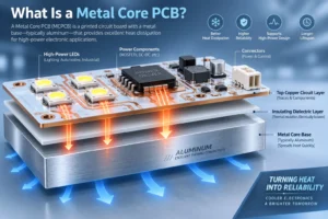
| Metal core rigid PCB | Aluminum or copper core for better thermal conductivity, especially LEDs | 1–4 |
Structure and Materials of Rigid Circuit Boards

The structure of a rigid printed circuit board embodies the precision engineering of modern design. It selects specific materials and employs specialized manufacturing processes, ensuring the circuit board achieves a robust physical construction. This approach significantly enhances the product’s mechanical strength, ensures long-term reliable electrical performance and enables cost-effective large-scale production.
Rigid PCB Stack-Up: Core Layers
Substrate/Core
- FR4 provides excellent dielectric constant, robust mechanical strength and cost-effective properties. This combination establishes it as the standard substrate for most rigid printed circuit boards.
- In the manufacturing of specialty printed circuit boards, aluminum substrates, copper substrates or polyimide substrates are commonly selected materials. These substrates effectively enhance the board’s thermal management capabilities and optimize its operational performance at higher frequencies.
Copper Layers
- Form the conductive circuit pattern. Copper thickness ranges from 1 oz/ft² (standard) up to 10+ oz for heavy copper or power boards.
- Increasing the number of copper layers of a circuit board can provide more available routing paths and correspondingly enhance the circuit’s current-carrying capacity.
Solder Mask Layer
- This material provides insulation for copper layers and prevents them from corrosion, effectively inhibits the formation of solder bridges and improves the overall solderability of soldering operations.
- Most commonly green, but black, white, red and blue are available.
Silkscreen
- Marks for component placement, test points, and reference designators. Essential for PCB assembly quality.
Surface Finish (ENIG, HASL, OSP, Immersion Silver)
- Applied to exposed copper for improved connection, corrosion resistance and manufacturability.
Rigid PCB Material Properties
| Layer | Common Material | Function | Specialty Option Examples |
| Substrate Core | FR4, polyimide | Structural, dielectric | Aluminum, copper, PTFE |
| Copper | Electrolytic copper | Conductive circuit pattern | Thicker copper, high-frequency foil |
| Solder Mask | Epoxy, polymer | Protect copper, solder prevention | High-thermal/UV-cure masks |
| Silkscreen | Non-conductive ink | Markings, reference, logo | UV-stable colors |
| Surface Finish | ENIG, HASL, OSP | Solderability, anti-corrosion | Immersion silver, gold, tin |
Rigid PCB Design Considerations
Every great rigid PCB design balances performance, manufacturability and cost. Here’s what you must consider for a successful, reliable, and efficient rigid circuit.
Key Design Decisions
- PCB stack-up: Planning the number of copper layers in circuit board design needs to incorporate signal routing requirements, ground layer design and power distribution schemes.
- Copper thickness: Designing high-current paths requires thicker copper layers. Standard-thickness copper layers can already meet the requirements for most analog and digital signals.
- Trace widths & spacings: Employ design rules for signal integrity and manufacturability; referenced in IPC-2221 standards.
- Solder mask and silkscreen legibility: Select contrasting colors and ensure no overlap with pads.
- Component layout: Keep sensitive circuits (RF/high-frequency PCB, analog) shielded and separated from noisy digital traces.
DFM/DFT Best Practices
- Collaborate with your PCB manufacturer early to optimize for their processes and prevent surprises.
- Avoid sharp trace angles and use teardrops at pad connections for mechanical durability.
- Plan for adequate pad sizes, vias and thermal relief for high-dissipation components.
Rigid PCB Manufacturing Process

Design and Photoresist Imaging
CAD-based PCB design is transformed into Gerber files, which program automated machinery for imaging the initial circuit pattern onto copper-clad laminate.
In the manufacturing process, a photosensitive resist is first uniformly applied onto the surface of the PCB substrate. Subsequently, ultraviolet exposure equipment selectively irradiates the circuit trace areas to be retained. The unexposed film in other regions is then removed during the developing step, thereby forming the precise circuit pattern.
Chemical Etching
Etching removes unwanted copper, leaving behind only the precise traces and pads required by the circuit design.
For multi-layer boards (a common pcb type for advanced circuits), each internal layer undergoes this process before lamination.
Lamination and Bonding
The etched layers are stacked with layers of FR4 substrate and bonded under heat and pressure—a step known as lamination.
This process creates the solid substrate and mechanical strength that distinguishes rigid PCBs from flexible pcbs.
Drilling Through-Holes & Vias
Precise drilling creates vias and through-holes for interlayer connections or through-hole component leads.
High-speed CNC drilling or laser drills are used depending on board complexity (especially in high-density multilayer designs).
Copper Plating and Via Metallization
Electroplating deposits copper inside all holes and vias, making them conductive and ensuring reliability across the board’s stackup.
Outer Layer Imaging & Etching
Similar to the inner layers, photoresist and chemical etching form the copper traces for the surface of the PCB.
Solder Mask Application
The solder mask layer (usually green epoxy or polyimide) is applied to insulate and protect the copper traces except at pads where components will be soldered.
This greatly increases the board’s durability and helps prevent solder bridges during assembly.
Silkscreen Printing
A silkscreen layer is added, providing important assembly and test markings. Ensure high contrast for pcb assembly quality.
Surface Finish (Solderability Enhancement)
A protective finish is applied—ENIG (Electroless Nickel/Immersion Gold), HASL, OSP, etc.—to improve solderability and shield exposed copper from oxidation.
Testing and Inspection
Automatic optical inspection (AOI), X-ray and electrical tests guarantee the pcb quality meets design and industry standards.
IPC-6012-compliant suppliers produce inspection logs you can review for rigid PCB fabrication traceability.
Depanelization & Final QA
After rigid printed circuit boards are separated from the manufacturing panel, they undergo final quality inspection. These inspections include visual examination, mechanical testing, and electrical performance verification.
Manufacturing Process Summary Table
| Step | Purpose | Enhances |
| Photoresist Imaging | Circuit pattern formation | Signal integrity, fine geometries |
| Chemical Etching | Define conductive paths | Circuit reliability, precision |
| Lamination | Build solid substrate | Mechanical strength, durability |
| Drilling | Create vias and holes | Connectivity, multi-layer functionality |
| Copper Plating | Metallize vias | Consistent interlayer conductivity |
| Solder Mask Application | Insulate & protect | Soldering, environmental resistance |
| Silkscreen Printing | Provide markings | Ease of assembly, diagnostics |
| Surface Finish | Protect copper, solderability | Longer shelf life, solder joint quality |
| Testing & Inspection | Detect faults | Reliability, certification |
Rigid vs Flex & Rigid-Flex PCB Types
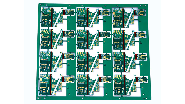
The design of modern electronic products increasingly emphasizes unique form factors, durability and cost optimization. Selecting the appropriate printed circuit board type directly impacts the product’s final performance and manufacturability.
Rigid PCBs vs Flex PCBs
- Rigid PCB: Rigid printed circuit boards use a solid substrate as their structural foundation, most commonly materials like FR4. This construction renders them physically rigid and unyielding, incapable of being bent or twisted. This characteristic provides a reliable foundation for application scenarios requiring high mechanical stability and efficient heat dissipation capacity.
- Flex PCB: Made from polyimide or polyester, enabling bending or folding in tight spaces. Used in applications where movement or 3D assembly is needed.
Rigid-Flex PCB
A rigid-flex PCB merges rigid circuit board and flex PCB technology:
- Rigid regions are used to bear dense or heavy electronic components. Flexible arm segments adopt flexible circuit materials to establish connections between rigid regions. This design enables the circuit to achieve assembly and adaptive movement in a three-dimensional space.
- Used extensively in aerospace, military, medical devices, consumer electronics (folding phones, cameras) and automotive controls.
IPC, Quality, and Reliability in Rigid PCB Manufacturing
Industry Standards and Certifications
- IPC-6012: The gold standard for rigid PCB manufacturing process, covering base materials, copper thickness, chemical etch, solderability and testing.
- IPC-6013: The design of rigid-flex printed circuit boards needs to simultaneously meet the reliability standards of both rigid regions and flexible regions.
- UL, ISO 9001, IATF 16949 (Automotive): Many sectors demand further quality system certifications for the best PCB results.
Guaranteeing Reliability
- Choose a pcb manufacturerwho documents all substrate materials, stackup, copper thickness, and test results.
- Use Class 3 (high-reliability) processes for aerospace, automotive, and medical circuits.
- Always design trace widths, vias and pad sizes according to circuit demands and manufacturer capability.
Applications of Rigid PCBs: From Consumer to Aerospace
Electronic Components Integration
Rigid PCBs are found in every industry, thanks to their durability, heat dissipation, and solid substrate support of sensitive electronic components. Common uses include:
- Consumer Electronics: Smartphones, tablets, computers, TVs employ multilayer rigid PCBs for processor, power and signal routing.
- Automotive: Engine and power electronics need heavy copper rigid boards for reliable current flow and thermal conductivity.
- Industrial Controls: PLCs and robot drives require robust stackup for noise immunity and mechanical strength.
- Aerospace: Rigid PCB with high glass transition temperature and vibration resistance for critical avionics or satellite control.
- LED Lighting: Metal core or aluminum rigid PCBs ensure better thermal conductivity and long LED lifespan.
- Medical Devices: Instruments like patient monitors or x-ray machines depend on rigid circuit boards for accuracy and stability.
PCB Assembly, Cost and Efficiency
Rigid PCB assembly includes both surface mount technology (SMT) and through-hole technology (THT), each chosen for component type, signal integrity and ruggedness.
- Solderability is enhanced by surface finishes and solder mask prevents unwanted bridges during mass assembly.
- Automated assembly(pick-and-place) increases accuracy and throughput in high-volume manufacturing.
Cost Drivers for Rigid PCBs
- Number of Layers: More layers = higher cost, but also more routing and functionality.
- Copper Thickness: Heavy copper PCBs cost more but are vital for high-current applications.
- Substrate Material: Specialty laminates (metalcore, polyimide) cost more but provide better thermal conductivity or reliability.
- Panel Size/Shape: Odd shapes or multiple designs per panel (panelization) affect overall cost-effectiveness.
Frequently Asked Questions
Q: Do all rigid PCBs use FR4 as a substrate?
A: While FR4 is the most common PCB substrate for its balance of cost, mechanical strength and electrical reliability, many rigid circuit boards use polyimide, aluminum, copper or high-frequency materials like PTFE for specific demands (e.g., thermal, frequency or durability requirements).
Q: What are the main differences between rigid, flex, and rigid-flex PCBs?
A:
- Rigid PCB: Built on a solid substrate material such as FR4 or aluminum; provides excellent mechanical support, great for static environments and easy to assemble.
- Flex PCB (Flexible PCB): Built on bendable materials like polyimide for use in moving or constrained spaces (wearables, folding phones), supporting unique 3D circuit designs but requiring special handling during assembly.
- Rigid-Flex PCB: Combines both rigid circuit board sections and flexible interconnects in a single board. Enables complex, high-density, space-saving applications in aerospace, medical, automotive and high-end consumer devices.
Q: How does copper thickness affect a rigid printed circuit board’s performance?
A: Thicker copper layers enhance current-carrying capability, allow for better heat dissipation and improve durability under thermal stress. Heavy copper is critical for high-power circuits, automotive and industrial controls, but adds cost and challenge to the manufacturing process.
Q: Is rigid PCB fabrication cost-effective compared to flex or rigid-flex pcb types?
A: For most high-volume, mechanically stable applications, rigid PCB fabrication is the most cost-effective solution. Flex and rigid-flex PCBs are typically more expensive to manufacture but may save money by eliminating connectors, cables or assembly steps in complex designs.
Q: What’s the role of the solder mask layer and silkscreen in circuit board reliability?
A: The solder mask insulates copper traces, protects against oxidation and helps prevent solder bridging during PCB assembly. The silkscreen layer provides vital markings for assembly, inspection and maintenance, directly impacting assembly quality and long-term servicing ease.
Q: How important is the stackup and lamination process for a multilayer rigid PCB?
A: Absolutely critical. Proper PCB stack-up and lamination ensure mechanical strength, minimize signal loss and support high-frequency or high-density designs. Poor lamination or stackup can cause warping, delamination or unreliable electronic performance.
Q: When should I consider a high-frequency PCB, heavy copper PCB or a metal-core PCB?
A:
- High-frequency PCB: For RF, telecom, radar and advanced data circuits requiring low signal loss and controlled impedance.
- Heavy Copper PCB: When your circuit needs to handle high currents, such as in industrial power supplies or automotive ECUs.
- Metal-Core PCB: Critical for LED lighting and power modules, where better thermal conductivity and heat dissipation are needed to maximize component life.
Conclusion
The rigid PCB remains the gold standard in circuit board technology for its versatility, cost-effectiveness and proven ability to deliver reliable, high-density circuit performance. Whether you’re building a simple LED driver, a multilayer aerospace board or a hybrid rigid-flex PCB for next-generation medical devices, understanding the manufacturing process, substrate choices and circuit design tradeoffs is key to success.
Modern PCB manufacturing supports a huge range of options—from simple, single-layer rigid boards to high-frequency, heavy copper or rigid-flex PCBs—empowering you to create reliable and efficient electronic products for any application.