Introduction
SMD components, or Surface Mount Device components, play a crucial role in shaping modern electronics. Integrated onto printed circuit boards (PCBs) by automated assembly, SMDs have revolutionized the functioning of electronic circuits by enabling compact size, higher component density, superior speed, and unparalleled reliability. Whether you’re a design engineer, repair technician, or hobbyist, understanding of SMD components is essential for successful circuit design, maintenance, and manufacturing.
This comprehensive SMD components guide covers essential topics such as the surface mount device definition, the difference between SMD and traditional through-hole components, key types like SMD resistor and SMD capacitors, fundamentals of SMD packages, PCB design and assembly, solder paste use, tips for accurate identification, and hands-on engineering advice—empowering anyone involved in electronics to excel in today’s industry.
What are SMD Components?
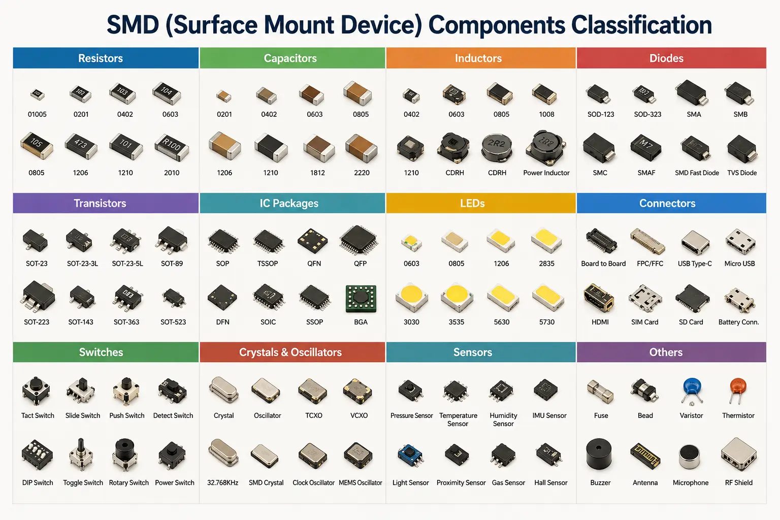
Based on our industry analysis, SMDs (surface-mount components) are compact components designed for direct mounting onto the surface of a circuit board, distinguishing them from through-hole components with leads. Common examples of SMDs include resistors, capacitors, inductors, diodes, transistors, and various integrated circuit chips.
SMT (Surface Mount Technology) is a manufacturing process for automatically mounting these surface-mount components onto a circuit board: high-speed pick-and-place machines first pick up and precisely position the components, followed by reflow soldering, which uses precise, simultaneous heating to solder them in place. The use of SMD components results in smaller, faster, and more reliable circuit boards, making them the cornerstone of high-density modern electronics like mobile phones, computers, and automotive controllers.
Key features of SMD components:
- Small size: SMD components are extremely compact, allowing more functional modules to be packed onto a single circuit board and enabling the creation of thinner, more compact products.
- Automate assembly: Pick-and-place machines handle high-speed pickup and precise placement; the entire process is fully automated, ensuring high efficiency and standardized quality.
- Shorter connections: Component leads and traces are short, resulting in lower parasitic capacitance and inductance and faster signal transmission; this makes them ideal for high-frequency circuits, such as those handling RF or high-speed digital signals.
- Enhanced reliability: Smaller solder joints result in correspondingly lower mechanical stress and higher reliability, reducing issues such as cold joints or fractures.
What is SMT (Surface Mount Technology)?
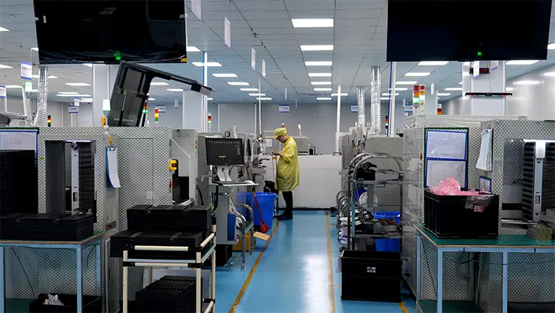
Surface Mount Technology is both a design philosophy and a manufacturing process that allows mounting of electronic component types directly on the surface of a PCB. Unlike through-hole technology, which uses long leads and requires manual or hybrid automation, SMT is optimized for speed, compactness, and ease of automating PCB assembly processes.
SMT process steps include:
- Solder paste printing: Solder paste is evenly applied across a stencil and precisely printed onto each solder pad.
- Pick-and-place: A pick-and-place machine retrieves components—such as resistors, capacitors, IC chips, diodes, and inductors—from their feeders and places them precisely onto the solder pads.
- Reflow soldering: The populated board is passed through a reflow oven, where the solder paste melts; upon cooling, the paste solidifies to form solder joints, thereby completing the soldering process.
- Inspection: After soldering, the boards undergo AOI (Automated Optical Inspection) or AXI (Automated X-ray Inspection) to verify solder quality and identify any defects.
Automate assembly via SMT allows for thousands of components per hour—orders of magnitude beyond earlier hand-soldering or through-hole processes. The SMT assembly process is now the backbone for everything from consumer devices to highly-reliable aerospace and automotive pcb design.
Why SMD Components Matter
SMD components play a crucial role in circuit designs where efficiency, cost, scalability, and small size are priorities. They support all major advances in miniaturized electronic circuits. Let’s break down why the use of SMDs is so widespread:
- Miniaturization: SMD technology enables the integration of miniature components into compact spaces, Components play a crucial role in devices like smartwatches and fitness trackers.
- Cost Efficiency: SMT is well-suited for automated, large-scale production, effectively reducing manufacturing costs while ensuring quality.
- Superior Performance for Advanced Circuits: Surface-mount components feature short signal paths, minimal parasitic effects, and low electromagnetic interference (EMI), resulting in faster signal transmission.
- Reliability: It is minimally affected by vibration and thermal cycling, making it resistant to cracking or cold solder joints. Whether for consumer electronics, high-reliability automotive electronics, or industrial equipment, SMT helps extend product lifespan.
History, Miniaturization, and Evolution
The rise of SMD component technology dates back to the late 20th century. As electronics demanded higher performance and higher component density, SMT emerged as the only way to keep up. Today, even PCB fabrication for prototypes is nearly always designed with SMDs in mind.
Did you know? Today’s smallest common SMD package sizes—like 0402 and 0603—are smaller than a grain of rice, yet they can handle realistic voltage and power needs for most digital electronic circuits.
Types of SMD Components: The Foundations

Understanding the basic types of SMD components is pivotal for any design, repair, or assembly work. The primary SMD component types on any PCB are:
Passive SMD Components
SMD Resistor
The SMD resistor is ubiquitous in PCB design. Available in package sizes from 0201 to 2512, SMD resistors serve to limit current, pull lines high/low, divide voltage, and set time constants in electronic circuits. Their values are printed directly on the body in 3- or 4-digit resistance value codes (e.g., “102” is 1kΩ, “4R7” is 4.7Ω). The symbol “ω” represents ohm, the unit of resistance.
- Standard package sizes: 0603, 0402, 0805
- Typical applications: Pull-ups, biasing, current sensing
- Example: A 0603 SMD resistor marked “103” converts to 10kΩ resistance value.
SMD Capacitors
Among SMD capacitors MLCCs (Multi-Layer Ceramic Capacitors), the X7R and C0G (NP0) types are the most commonly used due to their excellent temperature stability. Larger packages (such as 0805) are typically used for high-voltage or high-capacitance applications, while smaller packages are used where space is limited.
- Standard types: include ceramic, tantalum, and electrolytic capacitors; the latter two offer higher capacitance and larger physical sizes, making them common choices for applications requiring high capacitance, such as power supply filtering.
- Markings: A three-digit code printed on the capacitor indicates its capacitance. For example, “104” means “10” followed by four zeros (in picofarads)—resulting in 100,000 pF, or a decoupling value of 0.1 μ Small-sized MLCCs (such as 0402 and 0201) do not bear markings.
- Used for: Power supply decoupling (supplying instantaneous current to chips), filtering (smoothing voltage ripple), timing (setting frequency in conjunction with resistors), and RF coupling (allowing high-frequency signals to pass while blocking DC).
SMD Inductors
SMD inductors are used for suppressing electromagnetic interference (EMI), energy storage, and filtering. Like resistors and capacitors, they come in standard surface-mount packages, such as the 0603 and 0805 sizes. Inductance is typically expressed in microhenries (μH), and the components often feature a numerical code—such as “100” to represent 10 μH—read in a manner similar to capacitor codes, but with the unit being microhenries.
Active SMD Components
SMD Diodes
SMD diodes include rectifiers, voltage regulators (Zener diodes), Schottky diodes, and LEDs. They come in various package types, such as SOD-123, SMA, and SMB. Their circuit applications include rectification, voltage regulation, ESD protection, and visual indication.
SMD Transistors
SMD transistors include BJTs and MOSFETs (available in SOT-23, SOT-89, and SOT-223 packages). They are used for switching (turning signals or currents on/off), amplification (boosting small signals into larger ones), and logic control (working with other components to implement simple logic functions). Their low profile makes them ideal for ultra-thin designs, and they offer improved response speeds.
SMD IC and Advanced Components
Integrated circuits (ICs) can be considered the most “high-value” components on modern PCBs. Within a compact package, they integrate hundreds, thousands, or even millions of electronic components—including transistors, resistors, and capacitors—consolidating complex logic operations, data processing, and storage functions into a single small module. Common IC package types include SOIC, TSSOP, MSOP, QFP, QFN, DFN, LGA, and BGA. Each package type features a distinct pin arrangement and pad design. The choice of package depends primarily on the chip’s complexity, the number of pins, and available board space.
- The QFP-packaged chip on the circuit board is a microcontroller (MCU). Acting as the board’s “brain,” it integrates control logic, analog signal conversion (ADC/DAC), and various peripheral interfaces (such as UART, SPI, and I2C) into a single unit.
- In addition to the MCU, the board features other types of surface-mount ICs, such as operational amplifiers, logic gates, power management ICs, and RF transceivers. These chips utilize surface-mount packaging to save space and shorten signal paths, resulting in a more compact and reliable board assembly.
- Modern surface-mount ICs go beyond core functional circuitry; they often integrate ESD protection diodes, embedded resistors, and even voltage regulators (LDOs) directly onto the chip. This integration simplifies circuit design while reducing the Bill of Materials (BOM) cost and the number of potential points of failure.
Mechanical SMDs and Connectors
In addition to resistors, capacitors, and ICs, high-density PCBs also feature mechanical SMD components—such as surface-mount tactile switches and various connectors (board-to-board, board-to-wire, FPC, etc.). These compact, surface-mountable connectors are ideal for space-constrained portable devices. They enable modular product assembly, allowing components like screens, batteries, cameras, and keypad boards to be manufactured as independent modules that connect to the mainboard, thereby optimizing both assembly and repair efficiency.
SMD Packages, Codes, and PCB Implementation
Mastering SMD packages and codes is vital for anyone involved in electronics—whether you’re designing your own circuit boards, assembling kits, or troubleshooting a complex embedded system.
Standard SMD Package Families
| Package | Typical Use | Common Sizes | Application Example |
| 0603 | SMD resistors, capacitors | 1.6 × 0.8mm | Decoupling in circuit boards |
| 0402 | High-density, low-power passives | 1.0 × 0.5mm | Mobile phones, IoT sensors |
| 0805 | Power circuits, input filtering | 2.0 × 1.25mm | Automotive PCBs |
| SOIC, TSSOP | ICs, op-amps, EEPROMs | Varies | Controllers, A/D converters |
| QFP, QFN, BGA | Advanced IC, microcontrollers | Varies | CPUs, FPGAs, RAM, ASICs |
SMD Package and Size Chart
- 0402: For the smallest, densest PCBs in smartphones and wearables
- 0603: The “workhorse” size for most signal, analog, and logic circuits
- 0805: Used for power rail filtering, voltage reference circuits, and higher power requirements
SMD package size selection affects not just performance, but yield, manufacturability, and repair. Pick a standard SMD wherever possible, as “exotic” sizes can increase procurement times and assembly risk.
SMD Code Systems and Accurate Identification
- SMD resistor codes: Three digits (“472” = 4,700Ω), four digits for precision
- Capacitor codes: 3 digits (“105” = 1μF), sometimes marked with pF value or series code
- Inductors: Numeric or alphanumeric markings based on manufacturer; double-check with datasheets
- SMD diodes/transistors: Two- or three-letter manufacturer code, often requiring codebook lookup
- SMD ICs: Full or partial part numbers, batch codes, and date codes—identification often needs accurate datasheet referencing
If you’re identifying SMD components during PCB repair or failure analysis, always cross-reference both the layout/part markings and official code charts to avoid mistakes.
Identifying SMD Components: Techniques and Examples

Accurate identification of SMD component types is a fundamental skill when repairing, modifying, or reverse-engineering circuit boards. Many SMD components look identical; for instance, two SMD resistors might share the exact same physical dimensions, yet a difference of just one digit in their resistance code can result in a vast difference in actual resistance (such as 100Ω versus 10kΩ).
Visual Identification Tips
- For SMD resistor and SMD capacitors, size and code markings are the initial clues. Resistors are usually marked; capacitors less often.
- Regarding polarity markings for inductors and diodes: surface-mount (SMD) inductors sometimes feature a colored band, while diodes typically use a color ring or stripe to indicate polarity. Small notches or dots on SMD ICs mark the pin positions.
- The white silkscreen characters on the PCB surface represent the reference designators for each component; for example, resistors start with R, capacitors with C, diodes with D, and transistors (BJTs/MOSFETs) with Q.
Example: SMD Resistor Identification
A 0603 SMD resistor marked 103 means 10,000Ω = 10kΩ. A 0402 part labelled 474 is 470,000Ω (470kΩ). For SMD capacitors in power-supply circuits, you may see 106 (10μF), typically in a larger format like 0805 or 1206.
Use of Datasheets & SMD Codebooks
To confirm part values or determine mysterious parts, look up the marking in manufacturer datasheets or visit online SMD code databases. When in doubt, measure unknown resistors in-circuit (if possible) with a multimeter, but be mindful of parallel paths which can affect your reading.
SMD Polarity and Orientation
For advanced types of SMD components, orientation is critical. Diodes have a band for the cathode, while LEDs may also be marked with a triangle. Electrolytic and tantalum SMD capacitors show a “+” for the positive terminal. Misplacement often leads to instant circuit failure or reduced long-term reliability.
SMD Component Selection Guide for PCB Designers
Proper selection of SMD components requires:
- Knowing the required resistance value, voltage, capacitance, or current for every node in your circuit.
- Ensuring tolerance, temperature rating, and package match application and anticipated PCB assembly process.
- For high-frequency circuits, always check the parasitic characteristics of the package and keep traces short—especially for SMD capacitors used in GHz systems.
- Passive components such as SMD capacitors and resistors dominate most BOMs; prioritizing standard sizes like 0603 or 0805 improves yield and sourcing.
Selection Example: A 1% precision 0603-package SMD resistor is used for the feedback voltage divider to ensure accurate voltage sensing; a 10μF ceramic capacitor in an 0805 package is placed at the input or output to filter out high-frequency noise; additionally, a 4.7μH shielded SMD inductor is connected in series to suppress electromagnetic interference caused by switching noise.
Advanced Considerations
- Voltage Derating: For ceramic capacitors, use a rated voltage 50–100% higher than the actual circuit voltage for reliability.
- Power Derating: Never run SMD resistors at more than 60–70% of their rated power.
- Thermal Analysis: For power ICs or SMD transistors, use packages like SOT-223 or DPAK for better heat dissipation.
Why Accurate Selection Is Essential
Errors in the selection of values, packaging, or design of surface-mount components directly impact a circuit board’s performance, stability, and service life—particularly in applications such as automotive electronics, industrial control systems, and critical manufacturing equipment where reliability is paramount.
Soldering, Handling, and Rework for SMD Components
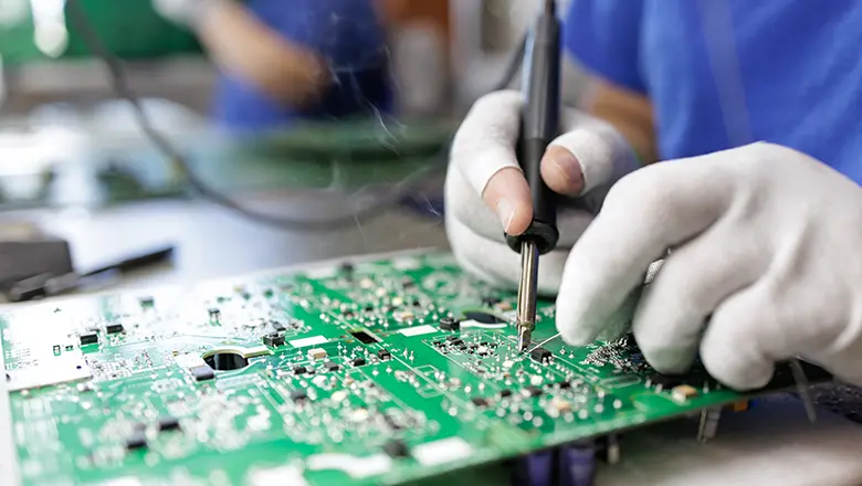
Even in fully automated SMT production lines, setting parameters—such as the temperature profile from solder paste printing to reflow soldering—relies on experience and intuition in addition to scientific principles. Familiarity with every stage of the process is essential to ensuring the highest quality for every board.
PCB Assembly: Key Steps
- Solder Paste Application: When using a stainless steel stencil to apply solder paste to the pads, uniformity is key. Inconsistent thickness can cause small resistors to lift (tombstone) or lead to solder bridging between adjacent pads during reflow soldering.
- Pick-and-Place Automation: The pick-and-place machine is equipped with an integrated machine vision system that enables the precise pickup and placement of components based on design files. Small components—such as 0603 and 0402 sizes—demand extremely high positioning accuracy, making high-precision robotic arms a standard feature.
- Reflow Soldering: The reflow oven operates according to a preset temperature profile to ensure the solder paste melts thoroughly and forms robust solder joints, all while preventing heat damage to the components. Lead-free solder pastes have higher melting points and require higher peak temperatures; consequently, strict control of the upper temperature limit is essential for temperature-sensitive chips, such as MEMS sensors.
- Inspection & QC: After soldering, AOI (Automated Optical Inspection) scans the surface to detect visible defects such as bridging and misalignment; X-ray inspection is used for components like BGAs—where leads are concealed beneath the chip—to check for voids or cold joints in the solder balls.
Soldering SMD, Hand-Soldering, and Rework
For prototyping, rework, or repair:
- Use a fine-tipped soldering iron, quality flux, tweezers, and magnification.
- Tack one end of an SMD resistor or capacitor, align, then solder the other side.
- For ICs, especially QFP or QFN, drag soldering and hot air may be necessary.
- Clean flux residue to prevent corrosion, especially important on high-density circuit boards.
- Always handle components with ESD protection (ground straps, mats) to safeguard sensitive ICs and transistors.
SMDs in Modern Electronic PCB Design: Advanced Applications
The integration of SMD components into modern electronic circuit designs has enabled an unprecedented level of innovation and efficiency across industries. In automotive PCBs, for instance, SMD components are chosen not just for their compact size and higher component density but also for their proven reliability in demanding environments. ECUs (Engine Control Units) feature hundreds, even thousands, of SMD resistors, SMD capacitors (including advanced ceramic capacitors), SMD inductors, SMD diodes, and rugged SMD connectors—all selected to withstand vibration, voltage surges, and thermal extremes.
Industrial, RF, and IoT Circuit Boards
In industrial electronics, the need for robust, scalable, and efficient solutions makes SMDs the standard. Circuit boards in PLCs (Programmable Logic Controllers), sensor systems, and high-frequency communications equipment rely on SMD transistors (such as SOT-23 and SOT-223 packages) for switching and signal processing. RF modules employ tiny 0402 and 0603 SMD capacitors for impedance matching and decoupling, ensuring optimal high-frequency performance.
IoT devices and smart sensors pack microcontrollers, voltage regulators, protection circuits, and wireless modules—all in compact SMD ICs and passive footprints, maximizing function in limited space and streamlining automated manufacturing.
Consumer Electronics and Mobile Phones
Modern electronics, from smartphones to laptops, exemplify what’s possible with SMDs. A mobile phone PCB may contain several thousand SMD resistors and capacitors, each as small as 0402 or even 0201, ensuring circuit miniaturization without sacrificing reliability. Integrated circuits (ICs)—including microprocessors and memory chips—typically use BGA or CSP SMD packages for high I/O and processing density, allowing manufacturers to automate assembly and achieve sleek, lightweight product form factors.
Visual Reference: SMD Package Size and Markings Chart
For fast and accurate identification during design, assembly, or repair, use a reference size chart. Below is a handy summary relevant to PCBs in all major fields:
| Package | Dimensions (mm) | Common Use Case | Typical Marking | Max Voltage (V) | Example |
| 0402 | 1.0 × 0.5 | RF/IoT/handhelds | 472, 104 | 25–50 | Cap/res |
| 0603 | 1.6 × 0.8 | General signal/power | 102, 473, 4R7 | 50–100 | Cap/res |
| 0805 | 2.0 × 1.25 | Power, control, filtering | 104, 1002 | 100+ | Cap/res |
| SOT-23 | n/a | SMD transistors, diodes | Manufacturer code | 40–100 | NPN/BJT |
| SOIC/TSSOP | Varies | ICs/OpAmps/MCUs | IC part number | Up to 40 | IC |
| QFN, QFP | Varies | Microcontrollers, FPGAs | IC part number | Up to 60 | IC |
| BGA | Varies | High-end processors | IC part number | Up to 100+ | CPU/RAM |
Resistor and capacitor code interpretation:
- 104 = 100,000 pF (capacitance) or 100 kΩ (resistance value)
- 4R7 = 4.7 Ω
- For ohm values less than 10, “R” is the decimal point (e.g., 2R2 = 2.2Ω).
Case Studies: Real-World SMD PCB Projects
1. Ultra-Dense IoT Sensor Node
Small form factor, wireless connectivity, battery operation—these requirements demand a design approach centered on SMD components. The designers chose 0402 SMD resistors, SMD capacitors, and a QFN SMD IC for the core MCU. A hot-swap FPC SMD connector enabled reliable maintenance in the field, while SMD TVS diodes protected inputs from static or transient voltage spikes. The use of SMD inductors and ceramic capacitors for power filtering supported a stable supply even under fluctuating environmental conditions.
2. Automotive Power Management PCB
Engineers selected SMD diodes in SOD-123 for voltage clamping, 0603 SMD resistors for current sense, and SOT-223 SMD transistors for robust high-current switching. The necessity for vibration-proof assembly led to wide-pad SMD packages and strict adherence to recommended reflow soldering profiles. Final inspection employed both AOI and thermal imaging to verify joint quality and heat spread.
3. Consumer Audio Amplifier
To maximize sound quality and compact size, this design used a mixture of thin-film SMD resistors (for low noise), tantalum and ceramic SMD capacitors (for signal and power supply decoupling), and large SMD inductors (for filtering in the power amplifier stage). The main amplifier IC, housed in a TSSOP SMD package, allowed direct connection to massive 0805 ceramic caps to reduce impedance and improve peak power.
Conclusion
SMD components are the foundation of every modern electronic circuit—making powerful, reliable, and compact products possible, from mobile phones to advanced automotive systems. Learning how to select, identify, and apply SMD resistor, SMD capacitors, SMD inductors, diodes, transistors, ICs, and connectors positions anyone involved in electronics for success in PCB design and manufacturing.
Understanding SMD component codes, package dimensions, solder paste and reflow soldering processes, and best practices in PCB assembly is vital for high-yield, reliable production and repair. As technology continues to push size and performance limits, mastery of SMD packages and their role in complex circuit boards becomes even more essential.
Frequently Asked Questions (FAQs) About SMD Components
Q: What are SMD components in a circuit?
A: SMD components are electronic parts mounted directly onto the surface of a PCB. They are widely used in modern circuits because they support compact layouts, automated SMT assembly, higher component density, and more efficient production compared with traditional through-hole components.
Q: What are the most common types of SMD components?
A: The most common SMD components include resistors, capacitors, inductors, diodes, LEDs, transistors, ICs, crystals, connectors, and sensors. Each component has a different function in the circuit, such as controlling current, filtering noise, storing energy, switching signals, or processing data.
Q: What is the difference between SMT and SMD?
A: SMD refers to the component itself, while SMT refers to the assembly process used to mount these components onto the PCB. In simple terms, SMD is the part, and SMT is the technology used to place and solder that part during PCB assembly.
Q: How do you identify different SMD components on a PCB?
A: Different SMD components can be identified by their package shape, size, markings, reference designators, and position in the circuit. For example, resistors are often marked with numbers, capacitors may have no visible markings, and ICs usually have printed part numbers or manufacturer codes.
Q: What does an SMD resistor do in a circuit?
A: An SMD resistor is used to control current, divide voltage, set bias points, and protect sensitive components. Although it is a small and simple part, it plays an important role in almost every electronic circuit.
Q: What is the function of an SMD capacitor?
A: An SMD capacitor is commonly used for filtering, decoupling, energy storage, timing, and noise reduction. In many PCB designs, capacitors are placed close to ICs to stabilize the power supply and reduce unwanted electrical noise.
Q: What are SMD diodes and LEDs used for?
A: SMD diodes allow current to flow in one direction and are often used for rectification, protection, and signal control. SMD LEDs are light-emitting diodes used for indicators, displays, backlighting, and visual status signals in electronic products.
Q: Which SMD package size should I choose for my circuit?
A: The best SMD package size depends on the PCB space, electrical requirements, assembly capability, and inspection needs. Smaller packages such as 0402 save space but require more precise SMT assembly, while 0603 and 0805 are often easier to source, assemble, inspect, and rework.
Q: Are SMD components less reliable than through-hole components?
A: No. Modern SMD components can be highly reliable when they are selected correctly and assembled with proper SMT processes. However, because SMD solder joints are smaller, PCB layout, solder paste printing, reflow profile, and inspection control are especially important.
Q: What are common problems with SMD components during assembly?
A: Common SMD assembly problems include tombstoning, solder bridging, cold solder joints, component shifting, wrong polarity, cracked components, and insufficient solder. Many of these issues can be reduced through proper PCB layout, DFM review, stencil design, and stable SMT process control.