Introduction
In every electronic circuit, whether simple or complex, there’s a single concept tying all the circuit components together: GND. Also known as ground, GND is the point in a circuit from which voltages are measured, forms the return path for current, ensures safety, and provides stability for the entire circuit. No matter if you’re designing a battery circuit, working with intricate integrated circuit layouts, or analyzing a circuit diagram, understanding GND and its role as a reference point is essential for proper circuit design.
From the role GND plays as the “zero-voltage reference point in electronic circuits” to how GND is used to prevent ground loops and interference, this in-depth guide will help you fully understand GND, its types, notation, problems, and the best ways to implement ground connections for robust electronics.
What Does GND Mean in Electronics?
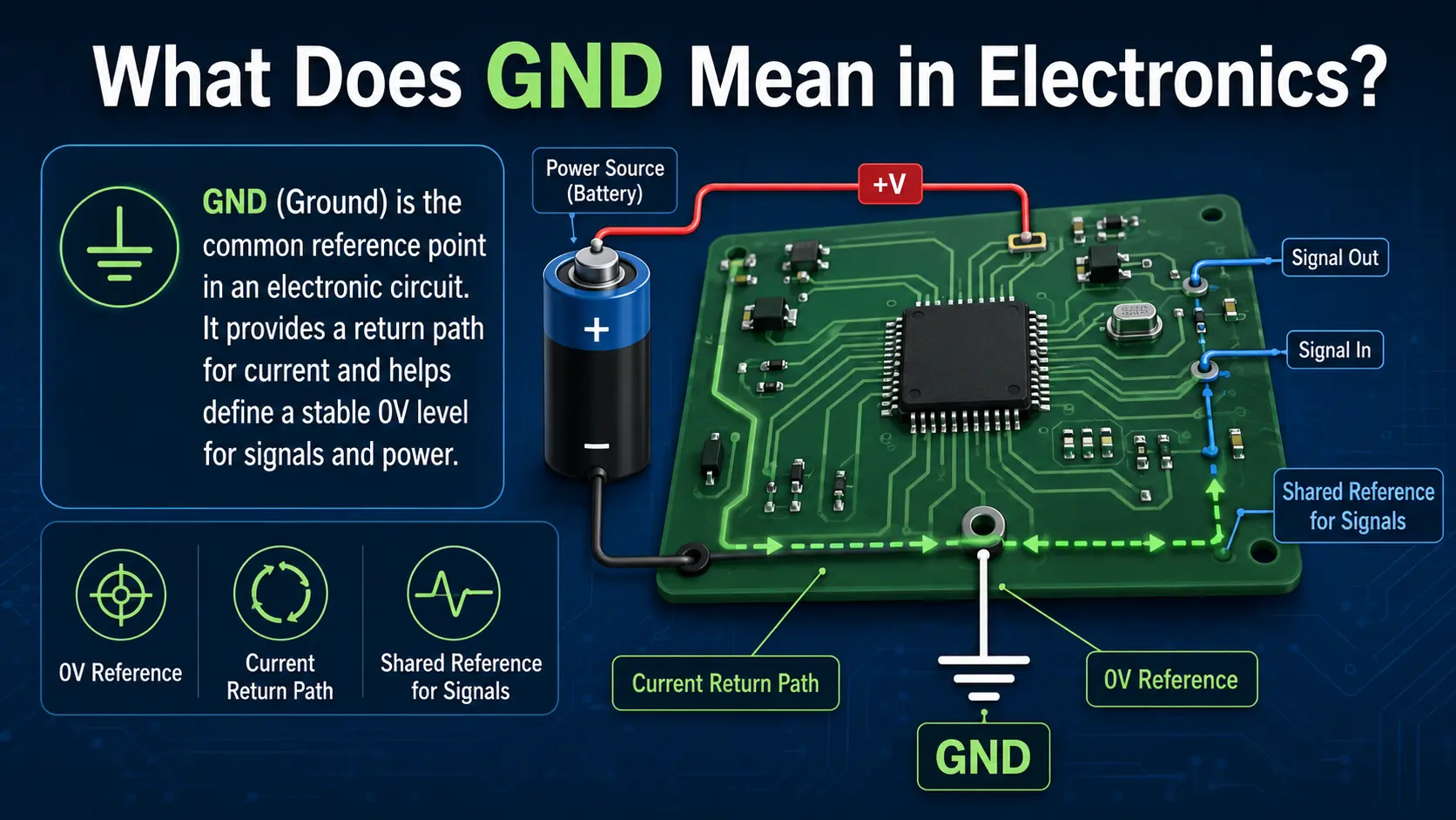
GND stands for ground—it’s the universal reference point in a circuit for all voltage measurements and provides a return path for current back to the power source. In most circuit diagrams, GND is typically shown as a special symbol representing a shared connection tying multiple points together.
GND full form: Ground Purpose of GND:
- Acts as a reference point in the circuit
- Ensures consistent voltages in the circuit
- Serves as the current return path for all circuit components
- Provides safety and helps prevent short circuit damage
For example: In a simple electrical circuit with a battery, current flows from the positive terminal through resistors, lamps, or other devices, and finally returns to the negative terminal of the power source through GND. GND provides the baseline by which every voltage in a circuit is measured. No matter where you take a voltage reading inside the circuit, it is made relative to GND—this is why the reference point is so important.
The Working Principle of GND in a Circuit
GND as the Zero-Voltage Reference Point
Every circuit shares the same baseline for measurement—called the reference point. Voltages in a circuit are always measured relative to GND. In a circuit diagram, this means drawing all voltmeters and measuring instruments with one probe connected to GND.
Example: Battery Circuit
In a battery-powered circuit, the negative terminal is usually connected to the negative terminal of the power source and set as the ground point. When the battery’s positive provides voltage (potential energy) to the circuit, current flows through the load (such as an LED) and returns to the battery via GND—completing the circuit.
Reference Point in Electronic Circuits
A reference point in a circuit is not always physically connected to earth; it’s an agreed-upon node to which all voltages are made relative to GND. In most designs, this reference is at the lowest potential—sometimes the chassis, sometimes the battery’s negative, sometimes tied to the literal earth ground.
Return Path for Current
A circuit to work depends on a complete return path for current. As current flows from the positive terminal of the power source through each part of the circuit, it loses energy, returning to the negative terminal via the ground connection.
GND Pin and Ground Pin
Most integrated circuits include a dedicated ground pin—or GND pin—that must be connected either to the system’s negative terminal, GND, or ground plane. Failure to properly connect this pin can halt the entire circuit or cause erratic behavior.
Current Flow, Short Circuit, and Fault Protection
In normal operation, current flow proceeds from the positive terminal, through the circuit, to GND. In a short circuit scenario, an unintended path between positive and GND causes a sharp rise in current flow, risking damage to electronic components and sometimes the entire circuit.
Why is GND Important in Circuit Design?
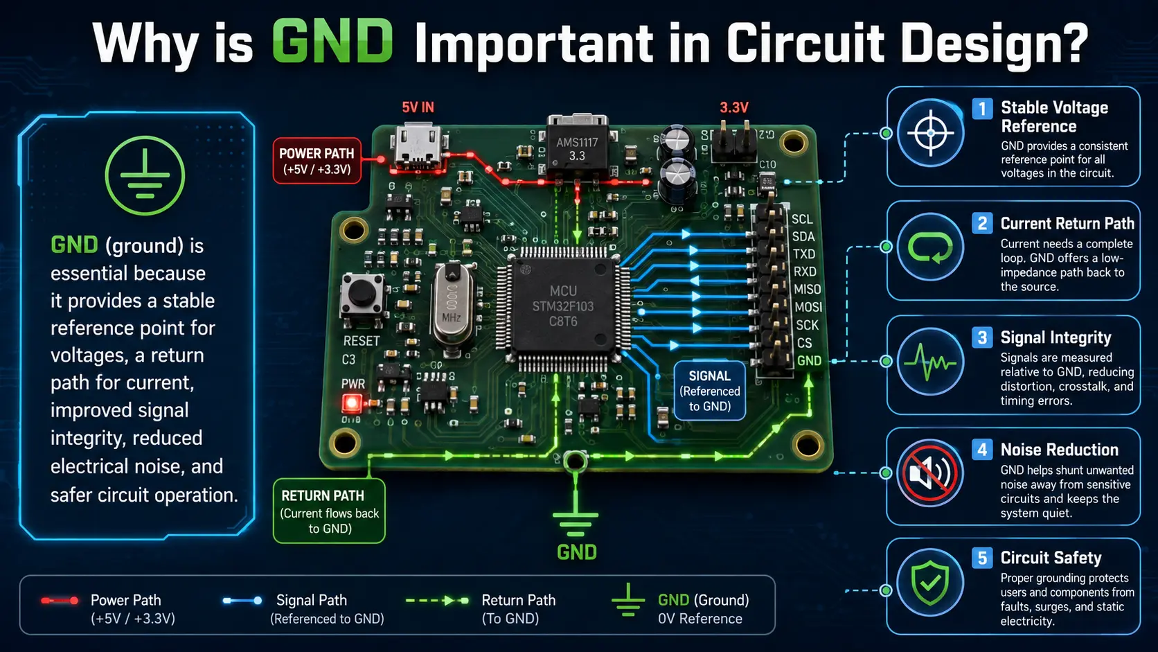
GND plays a critical role in every modern circuit design, influencing everything from power supply stability to safety and noise rejection. Here’s why GND is important:
1. Providing a Universal Reference
All voltages in a circuit are measured relative to GND. Without a solid reference, devices can’t communicate, sensors give erratic results, and circuit stability is compromised.
2. Return Path and Completing the Electrical Loop
GND serves as the return path for current, completing the circuit and making it possible for current to flow and the circuit to function.
3. Safety Mechanism
A strong ground connection prevents dangerous voltages from appearing on the chassis. In the event of a short circuit, GND routes fault current away from sensitive electronic devices.
4. Stability and Noise Reduction
A well-implemented GND and ground plane suppresses electrical noise (EMI), protects against voltage spikes, and ensures reliable data transfer in analog and digital systems.
5. Preventing Ground Loops
A ground loop arises when there are multiple paths to GND at different voltages. This can create unwanted currents, especially in audio circuits and analog circuits, leading to hum and unpredictable behavior.
Types of Ground in Electronic Circuits
There are different types of GND, each serving a specific purpose to optimize the performance of electronic devices and circuits.
| Ground Type | Description & Use case |
| Earth Ground | Tied to physical earth for safety & lightning protection in AC mains, power distribution systems. |
| Chassis Ground | Connected to the device’s frame or enclosure, shields against interference. |
| Signal Ground | Reference for sensitive signals, commonly used in analog circuit and mixed-signal designs. |
| Analog Ground | Ensures noise-free operation in delicate analog sections; kept separate from digital when possible. |
| Digital Ground | Serves as return for digital logic currents, kept apart from analog ground to avoid interference. |
| Power Ground | Used as the reference return for high-current loads or switching devices. |
| Floating Ground | Isolated from earth/other grounds—common in battery-powered or opto-isolated circuits. |
| Star Ground | All local grounds connect to a single point (“star”) to minimize ground loops. |
| AC Ground | Reference for AC signal returns in oscillators, amplifiers, and test gear. |
Why So Many Types of Ground?
Having different types of ground prevents high currents, digital switching noise, or external surges from interfering with the clean signal reference needed in analog and digital circuits.
Earth Ground vs Signal Ground
- Earth ground: Connected to a ground rod or earth plate; prevents electric shock.
- Signal ground: Isolated inside the device for a quiet, noise-free reference point.
Symbol in circuit diagrams: The earth ground symbol has different horizontal lines, while signal ground is usually a triangle. Always check which one your circuit diagram uses!
Reference Point in Electronic Circuits: Why is it Essential?
Every electronic circuit requires a reference point in a circuit—a specific spot to which all voltages are compared. This reference point in electronic circuits is normally GND. Setting and maintaining a solid reference is essential for:
- Accurate signal measurement: For example, a microcontroller’s ADC reads “zero” when its input equals the GND pin (the reference point).
- Consistent logic levels: All logic decisions in digital ICs depend on voltages measured relative to GND.
- Safe operation: Any change in the reference point in a circuit can result in “floating voltages” or dangerous potentials appearing where they shouldn’t.
- Performance of electronic devices: Sensors, amplifiers, and comparators must reference their outputs and thresholds against a known zero-voltage reference point in electronic circuits.
Even a small voltage shift at the ground point can wreak havoc in high-performance or precision circuit design, causing communication errors, noise, or even physical damage.
GND Implementation in Circuit Boards and ICs
The implementation of ground in circuit boards and integrated circuits is a cornerstone of modern electronics.
Ground Plane and PCB Design
A ground plane is a large area of continuous copper on a PCB, serving as a massive, low-impedance return path for signals. In high-speed or mixed-signal designs, the ground plane ensures that every part of the circuit has a stable reference, as well as a low-resistance return path for current. Not only does this improve circuit stability, but it also helps minimize EMI.
Why is the ground plane important?
- It equalizes potentials throughout the entire circuit.
- Reduces interference between analog and digital sections.
- Prevents voltage build-up or differential voltages between regions of the board.
- Boosts circuit performance and reliability.
GND Pin, Ground Pin, and Connections
All ICs have a ground pin (or “GND pin”) that must connect to the ground plane or the reference node. Incorrect, loose, or missed GND connections are among the most common, yet easily overlooked, reasons that a PCB or internal circuit fails.
Ground connection tips:
- Always use short, wide traces for ground connections to reduce resistance and inductance.
- On breadboards, ensure every GND section shares a common reference.
- In a battery circuit, always return all grounds to the battery’s negative terminal or a single star GND point.
How GND Affects Circuit Performance
GND plays a direct, critical role in every aspect of circuit performance:
- Signal integrity: Good grounding ensures that data and control signals maintain their shape and timing, especially important in fast analog and digital systems.
- Noise immunity: A proper ground connection—especially through a large ground plane—absorbs EMI and prevents stray signals from affecting sensitive nodes.
- Fault protection: When a fault current occurs (e.g., due to a short circuit), a low-resistance ground safely routes energy away, protecting devices.
- Voltage regulation: All power rails are stabilized when referenced to a solid ground, avoiding unexpected voltage drifts.
- Stability in integrated circuits: Digital logic, op-amps, and microcontrollers depend on a stable GND to function correctly.
What happens if GND is poor or missing?
- You may encounter logic errors, resets, or misread sensors in analog and digital systems.
- Analog outputs will show noise or offsets.
- Voltages might measure incorrectly, because nothing is referenced properly to GND.
- Physical damage is likely in a short circuit without a solid return path.
Even a small resistance between ground points can introduce enough voltage offset to affect circuit operation—especially in precision analog and digital interfaces.
Common GND Problems and Troubleshooting
Despite best practices, GND issues can still arise and affect circuit performance. Let’s explore the most common cases and how to troubleshoot GND issues.
Ground Loop
A ground loop happens when two different ground points are at slightly different potentials, allowing unintended “loop currents” to flow through equipment. In audio and measurement circuits, this often results in a low-frequency “hum” or erratic sensor readings.
Troubleshooting Ground Loops
- Connect all ground returns to a single star point to eliminate voltage differences.
- Use differential amplifiers, isolation transformers, or opto-isolators where cables run between systems on different earth grounds.
Floating Ground
A floating ground (no physical connection to global GND) is common in battery-powered circuits or isolated parts of equipment. This can cause nodes to sit at unpredictable voltages, especially if exposed to stray fields or static.
Solution for Floating GND
- Provide a deliberate ground connection to stabilize voltages.
- Use a pull-down resistor to tie floating points to the main ground.
Faulty Ground Pins or Connections
Broken solder joints, corroded wires, or missed vias can disconnect the GND pin of an integrated circuit or module.
Diagnosing Ground Pin Issues
- Perform a continuity test from each device’s GND pin to the main ground plane.
- Visually check solder joints for cracks or cold spots.
Common GND Mistakes in Circuit Board Design
- Daisy-chaining GND lines (rather than using a ground plane) in high-speed circuits
- Failing to join analog and digital grounds at a single star point
- Routing sensitive analog signals alongside noisy digital ground returns
Best Grounding Practices in Analog and Digital Circuit Design
Here’s a summary table highlighting the most effective GND strategies and tips for modern circuit boards:
| Practice | Benefit |
| Single-point (star) grounding | Prevents ground loops and voltage differences |
| Solid ground plane | Maximizes return path efficiency, minimizes EMI/EMC |
| Separate analog & digital ground planes | Minimizes noise coupling in mixed-signal systems |
| Wide, short traces for power ground | Prevents voltage drop, handles high current |
| Use of guard rings and shielding | Protects high-impedance and low-level analog signals |
| Always place decoupling capacitors between VCC and GND | Ensures local power filtering |
| Chassis ground at one location, tied to earth ground | Guarantees safety and avoids loops |
Real-World Tip
If you’re designing an electronic system with both audio (signal ground) and microcontroller sections, run all signal grounds to a single star point at the input connector, and keep them separate from power or digital ground returns until that point.
FAQs About GND in Circuits
Q: What does GND mean in electronics?
A: GND in electronics means ground, the reference point against which all other voltages are measured in a circuit.
Q: How is a ground symbol shown in circuit diagrams?
A: The ground symbol typically uses three horizontal lines, a triangle, or a downward arrow depending on type (earth, chassis, or signal ground).
Q: Is GND always the same as the negative terminal?
A: Often, especially in DC and battery circuits, GND is tied directly to the negative terminal of the power source. However, in complex systems, GND may be at a different potential, especially if earth ground or chassis ground is used.
Q: What’s the purpose of GND in analog and digital circuits?
A: In analog, GND provides a steady reference for low-noise performance. In digital, GND ensures logic levels are accurate and allows fast return paths for switching currents.
Q: How do you troubleshoot GND issues?
A: Check for continuity between ground pins and the main ground plane, look for floating or disconnected GND points, measure voltages relative to GND pins, and inspect for ground loops.
Conclusion
Understanding what GND is in a circuit and its crucial role as a reference point in electronic circuits is the foundation of all circuit design—whether you are a hobbyist, student, or professional. Proper GND practices ensure every circuit functions safely, reliably, and with optimal performance. A grounded approach in both design and troubleshooting leads not only to robust electronic devices but also ensures the long-term stability and safety of every part of the circuit.
Whenever you design, build, or repair an electronic device, remember: GND is more than a wire or a symbol—it is the silent backbone of every electronics project. Always respect GND, carefully plan ground connection strategies, and your circuits will reward you with reliability, safety, and performance.