An HDMI RF modulator may look simple, but the boards do a lot of work. After receiving the HDMI signal, it gets processed and finally sent out of the Coaxial output as a radio frequency signal. For this to be carried out cleanly by the boards, there needs to be a stable circuit path with clean grounds and controlled heat with appropriate PCB Materials.
If the board is made of weak board materials, the outputs may lose clarity. It may end up dissipating a lot of noise, heat or even lose the signal completely. This is why material selection and PCB design are crucial for every HDMI modulator.
Why PCB Design Matters Before Material Selection
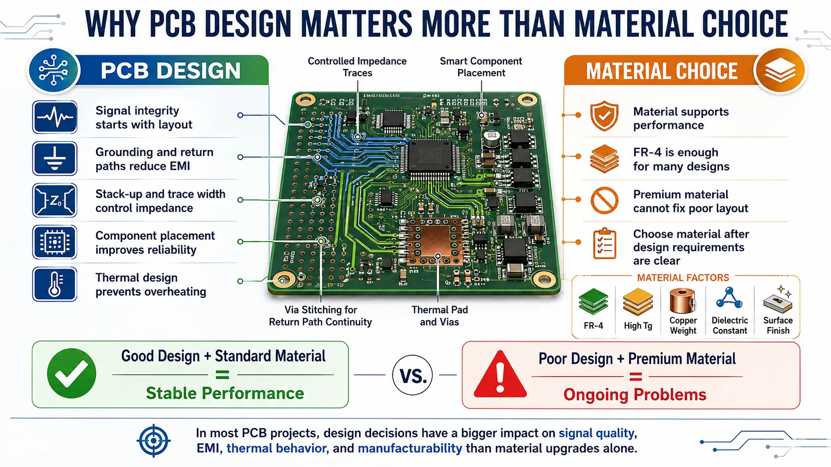
Most of the competitor materials talk of only FR4, Rogers, PTFE, and Ceramic. But in a typical HDMI RF modulator, providing only the appropriate materials doesn’t solve the problem. The design has to be right too.
Good PCB design provides a clean path for the signal. HDMI signals and RF Outputs have to remain stable and safe from interference, and therefore the design has to appropriately control impedance and interference.
PCB Materials for RF greatly impact signal loss, impedance, and thermal performance, as well as the ease of the boards being produced. The loss tangent and dielectric constant are critical for RF because of their impact at lower frequencies.
It cannot be stressed enough that the best board gets the best job done, and is not the one with the most expensive materials, but the one where all the parameters come together and work in unison: heat management, grounding, routing and the rest.
Signal Flow from HDMI Input to RF Output
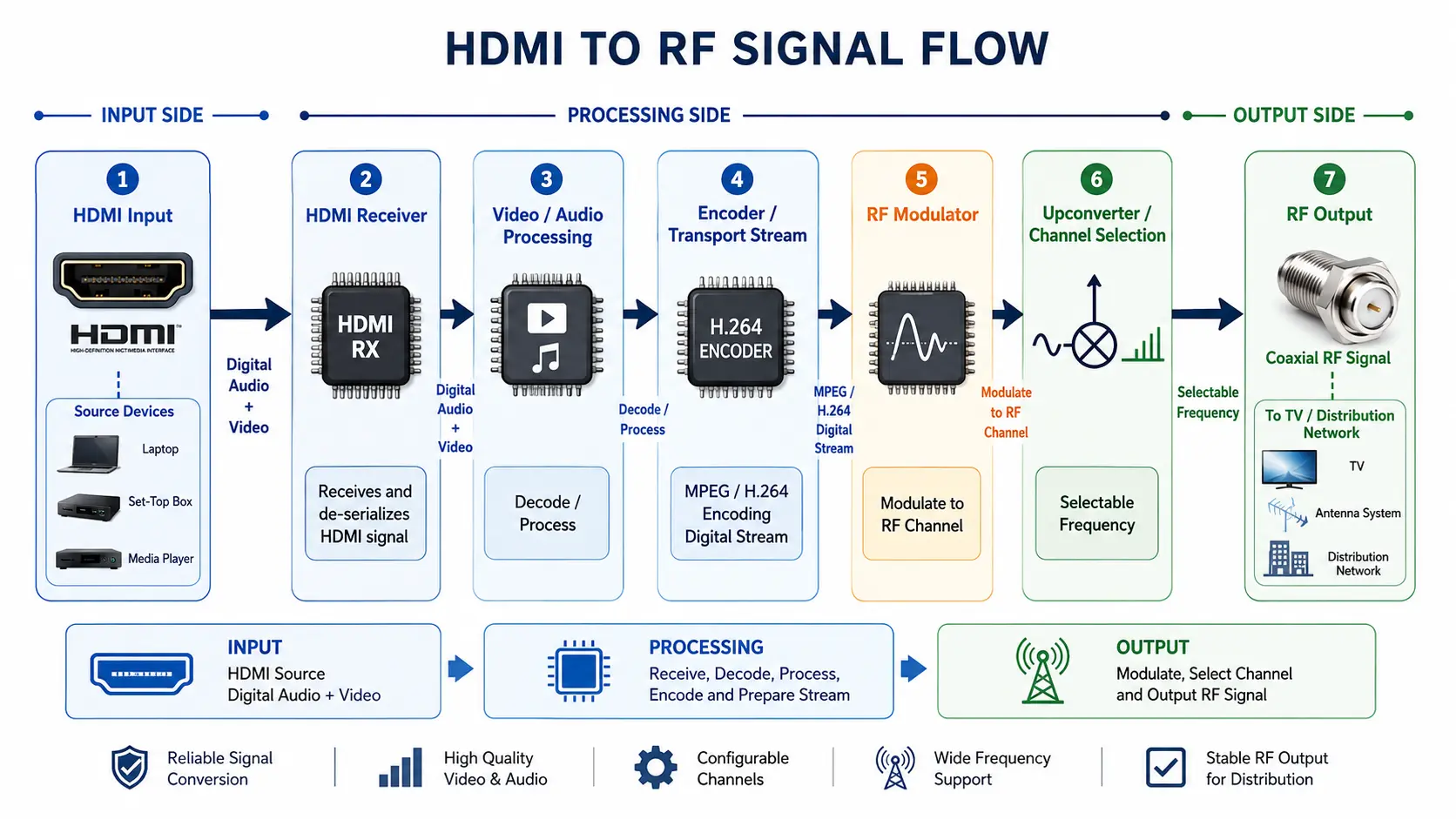
The inner workings of a modulator HDMI circuit are fascinating. The HDMI input will contain digital video and audio. The circuit translates this signal to an RF output, which can then be transmitted via coaxial cable.
This signal path will need to be short and kept free of noise. Trace length will contribute to loss that will degrade the signal. Crosstalk can be caused by poor trace spacing. EMI problems can occur with poor grounding, which can affect the output.
● HDMI Side
The HDMI side will contain a lot of fast signals. As such, controlled impedance with excellent routing will be a requirement. Fast signal routing will need to avoid sharp angles, poor trace spacing, and routed reference planes.
● RF Side
On the RF side, routed signals will need to be low-loss and well-grounded to control the consistent behaviour of the materials used. This side will be very sensitive to design.
● Power Side
Power circuits will need to be isolated from RF signal circuits. Power circuit noise can disturb RF and video signals.
Choosing PCB Materials Based on Real Use
This will affect the choice of PCB materials for the HDMI RF modulator. For example, a home-use modulator will have a lower-cost board than a modulator used for professional broadcasting.
Basic devices can use FR4. It is low-cost and easy to make, but has high signal loss at high frequencies. For heat, High-Tg FR4 is better. Rogers and PTFE are better for RF, as they have lower loss and better stability for RF and higher frequencies. For higher-frequency designs, RF material guides usually show stable dielectric properties, a low dissipation factor, and thermal stability as important factors.
Stackup Planning for Stable RF Performance
The layers of a PCB are referred to as the stackup, and can be one of the most important design choices. Poor stackups can be a source of noise and unpredictable impedance.
A two-layer board can be used for low-cost products. However, advanced HDMI RF modulators often need boards with many layers. A multilayer PCB aids EMI control, cleaning routing and grounding.
A solid reference plane must be routed for RF traces, and a stackup plan with controlled impedance and planned power and ground layers helps quiet the signal and maintain a stable design.
Hybrid stackups may incorporate fr4 for simpler sections and RF-grade material for RF sections. This can be a good way to control costs and maintain performance.
Heat Control and Alumina Density in Board Design
An HDMI RF modulator may be used for long periods of time in hotels, schools, control rooms, and various RF and TV System interfaces. Heat can slowly damage the performance and stability of the modulator and may cause the board to warp.
Certain PCB materials can help protect circuits and improve thermal dissipation. High-Tg FR4 can withstand more heat than FR4. Rogers material can help with stability in RF sections. Ceramics can improve design integrity in higher temperature environments.
Alumina ceramic is used in some advanced boards. Alumina density is important and can affect strength, insulation, and thermal behaviour of a modulator. Stronger ceramic structures can improve modulator performance while managing heat more effectively.
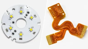
Rigid Flex PCB for Smaller Modulator Designs
When a more compact modulator is necessary, a Rigid Flex PCB is a good option. These boards integrate hard sections with flexible circuitry and are great for fitting circuits into tighter, more space-constrained areas.
Modern HDMI RF modulators tend to be compact. They may feature integrated HDMI input, RF output, shielding, buttons, a display, and power circuitry all housed within a small case. A Rigid Flex PCB leads to a significant reduction of both cables and connectors in the device.
Reliability is better with fewer connectors, as this leads to fewer failure points. It may also make assembly easier. Because Rigid Flex PCB construction provides an excellent advantage, it is particularly superior in compact designs. The advantage provided should determine if the greater cost is warranted.
Printed Circuit Board Repair and Service Life
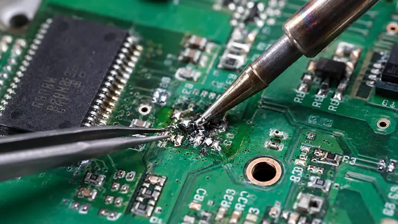
Choice of material influences printed circuit board repair, as some boards can be a greater repair challenge than others. FR4 is an easier circuit board material for technicians. Damaged pads, traces, and solder joints can be easily repaired.
RF-grade materials are more challenging. Rogers, PTFE, and ceramic boards need more care. These materials can be RF viable with less concern, but repair integrity and the RF grade can be challenged with poor soldering and repair techniques.
Good designs minimise repairs. Strong solder joints, quality connectors, clean groundings, and good heat control lead to long service life. A board that has a longer service life is better than a board that merely has an easy repair.
Design Mistakes That Can Hurt Modulator Performance
No amount of quality PCB materials can save a faulty design. HDMI RF modulators are especially sensitive to design issues.
Common design mistakes include routing RF traces too close to power sections and using weak grounds. Poor control of RF trace impedance and poor design of the heat paths can lead to instability and low signal quality.
Common Mistakes
Listed below are a few examples of design mistakes that can adversely affect the performance of an RF PCB.
- Poor quality materials in high frequency sections
- Long RF traces
- Poor impedance control
- Power circuits routed close to RF paths
- Poor shielding
- Poor thermal vias
- Material selection based solely on cost
Conclusion
Material selection and design must be optimised to balance costs. Good PCB materials help reduce losses and improve heating and RF stability, but good design and good grounding are just as important.
FR4 PCB works for simple products. For clean RF output, you would have to work with Rogers and PTFE. As for high-temperature designs, you have to consider alumina and ceramic. Lastly, Rigid Flex PCB works for designs with limited space. PCB repair is much easier when the design is meant for long-term servicing.
A reliable modulator HDMI product is not just one material. It is a smart choice of materials, and a plan of design that is routed and grounded with care.