
Two chips can share the same silicon yet act very differently on your assembly line. The difference often comes down to one thing: the package. TQFP is one of the most common answers, and one of the easiest to get slightly wrong. Its thin, gull-wing body fits snugly on boards, making inspection easier. However, pitch options range from 1.0mm to 0.4mm. A mismatched footprint can turn a good chip into a rework issue.
Here, we outline its dimensions, pin pitch, and footprint needs. We also show where it excels and where it falls short compared to its nearest alternatives.
What Is a TQFP Package?
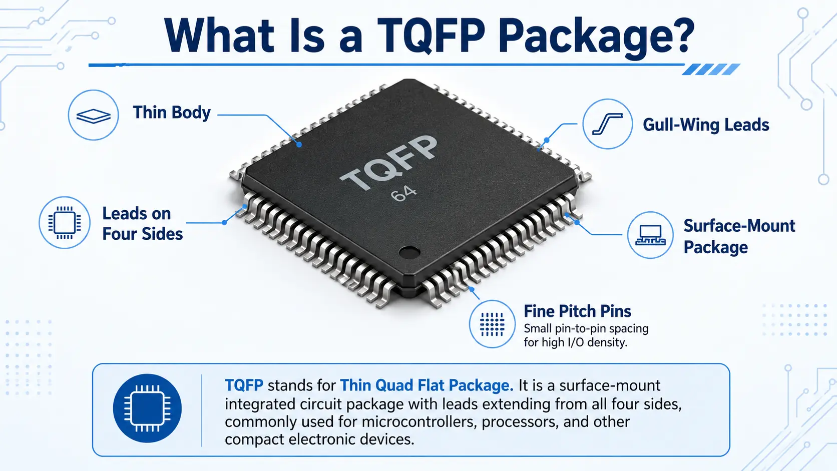
Imagine a skinny microcontroller with pins on all four sides. Most engineers think of that form first. TQFP (Thin Quad Flat Package) is the abbreviation for the surface-mount IC package made in exactly that shape. That is, its leads are in a “gull-wing” shape, that is, they go out and downwards, like a bird’s wing.
The important thing here is the word “thin”. Typical QFP thickness is usually 2.0mm to 3.8mm. But this variant remains at just 1.0mm. So it is good for slim and space limited designs.
It is used by engineers for microcontrollers, FPGAs and other medium-density chips. Because each pin is on the outside edge, it is easy to inspect and test each pin. This is a real plus when it comes to quality checks, especially on high mix production lines.
So what is TQFP? Just remember thin, four sided, flat. That’s what makes this package so common in compact electronics.
TQFP Package Dimensions and Pin Pitch
Pin pitch – distance between the center of two adjacent pins. The pitch options for this package type are 1.0mm, 0.8mm, 0.65mm, 0.5mm and 0.4mm. A smaller pitch means more pins in the same space. But it also means soldering takes more skill and better equipment.
Body sizes range from 5mm x 5mm to 20mm x 20mm . The pin counts are in a similar range. A basic chip can have as few as 32 pins. The larger ones, used for FPGAs or complex logic, can have as many as 176 pins.
Here is a quick reference table:
| Pitch | Typical Pin Count | Common Use |
| 0.8mm | 32–44 pins | Simple peripheral ICs |
| 0.5mm | 64–144 pins | Standard microcontrollers |
| 0.4mm | 176–256 pins | High-density logic, FPGAs |
Before you finalize your design, always check the datasheet first. Pitch and pin count vary between manufacturers, even within similar chip families. This small step can save you from a costly footprint mismatch later.
Common Microcontrollers Available in TQFP Package
It is the format of many popular microcontrollers. If you work with Arduino boards or similar embedded systems you have probably already used one without knowing it.
Popular TQFP Microcontrollers
| Chip | Pin Count | Typical Application |
| ATmega328P / ATmega328P-AU | 32 pins | Arduino Uno-class boards |
| ATmega2560 / ATmega2560-16AU | 100 pins | Arduino Mega-class boards |
| ATmega32U4 | 44 pins | Arduino Leonardo and Micro boards |
| ATtiny3217 | 24 pins | Compact, low-power embedded designs |
These chips remain popular for one simple reason. They are easy to hand solder and they are easy to visually inspect as well. So they’re excellent for prototyping, low volume runs and hobbyist projects as well.
Why are Package Suffixes Important?
If you have one of these chips in your BOM already as TQFP, nail down the exact package variant early, it’ll save you a headache later. Most suppliers have the same chip in different packages so it is well worth checking that part number suffix well before the order goes out.
It’s a little thing, but it trips people up more than you’d think.
See the ATmega328P vs the ATmega328P-AU, same silicon inside, but that “-AU” is what tells you it’s the TQFP package with lead free finish. Make that distinction wrong during sourcing and you may not find out about the BOM error until the parts are literally on your desk. Better to verify the suffix against your schematic before the PO is issued, not after.
TQFP Footprint and PCB Layout Tips

Getting your footprint right will save you from costly mistakes. Use these guidelines for a solid layout:
- Always use the land pattern recommended by the manufacturer for your TQFP package. For example, small variations in pad length may affect the quality of the solder joint.
- In the meantime, use a stencil of around 130 to 150 microns thick for 0.5mm pitch parts. Keep at 130 microns or less for 0.4mm pitch parts.
- The TQFP package is good for simple 2 or 4 layer boards because it uses standard traces instead of microvias. This will lower the overall cost of your fabrication.
- To help prevent placement errors during assembly, a visible index dot or silkscreen marker is provided.
- Proper spacing between traces near fine pitch pads. This step therefore greatly reduces the chance of bridging.
- Pads that are too wide or too narrow can cause tombstoning or uneven solder fillets, so get close to the datasheet spec.
Common Footprint Mistakes to Avoid
These small details make a real difference. In fact, most soldering defects are caused by a footprint or stencil mismatch not the component.
TQFP vs LQFP vs QFN
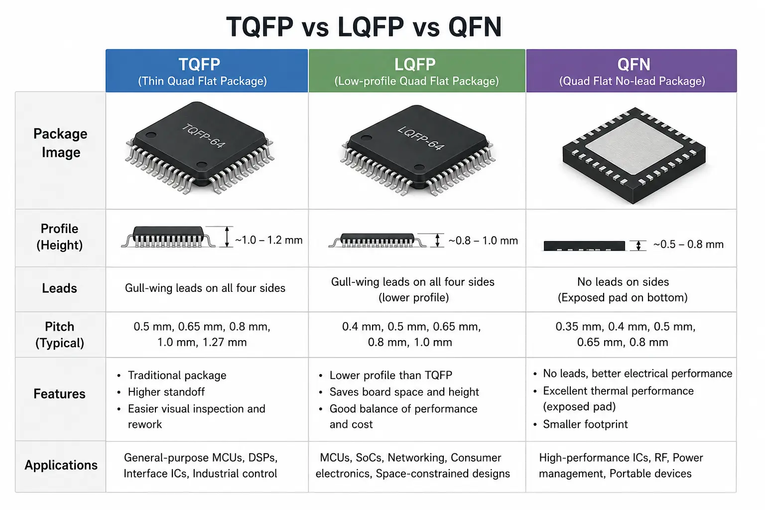
Engineers often compare this option against two close alternatives: LQFP and QFN. Here is how they differ:
| Package | Thickness | Leads | Best For |
| TQFP | 1.0mm | Gull-wing, all four sides | Slim boards, easy inspection |
| LQFP | 1.4mm | Gull-wing, longer leads | Prototyping, easier hand soldering |
| QFN | Very low profile | No leads, pads underneath | Ultra-compact, high-volume designs |
Which Package Should You Choose?
LQFP is often better for easy rework and low-volume flexibility. But if board space is the main concern, QFN generally wins. If you’re looking for a good compromise of thinness, easy inspection and mature manufacturing support, the TQFP package still makes a reliable middle ground.
But remember, moving from one kind of package to another is not always a simple switch. Even if the pin count is the same, the footprint, lead length and thermal pad requirements can vary. So always check compatibility before substituting one for another.
Cost Considerations
Cost is also a factor in this decision. Gull-wing packages usually cost less to assemble than leadless parts. They tolerate small misplacements better. On the flip side, QFN needs stricter process control and improved equipment. This can raise your assembly cost per unit, especially for smaller production runs. The forgiving lead style is safer for teams shifting from prototype to low-volume production.
Soldering and Assembly Considerations
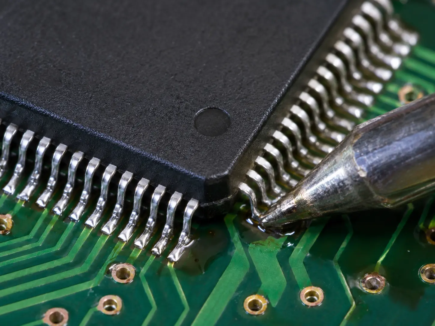
This package type works well with standard reflow soldering. Still, a few points deserve your attention.
Hand Soldering vs Automated Placement
Hand soldering gets harder as pitch shrinks. At 0.5mm or below, most teams rely on automated pick-and-place equipment instead of manual work. Therefore, rework also requires extra care. Short leads make single-pin repairs tricky, so many manufacturers prefer full component replacement over spot fixes.
Inspection, Rework, and Flux Application
Inspection is still pretty simple. All pins are exposed, allowing standard AOI (Automated Optical Inspection) to identify bent leads or solder bridges without X-ray. But that keeps quality control fast and cheap, especially as regards leadless packages.
Also, always spread the flux evenly before placing. This step improves wetting and helps prevent voids or weak bonds during reflow. Used with the right stencil it means a much higher first pass yield.
Final Thoughts
The TQFP package is a good compromise between small size, ease of inspection and manufacturing maturity. It is compatible with popular microcontrollers like the ATmega328P, ATmega2560 and ATtiny3217 and fits well in prototyping and production workflows.
Mind your angle. Layout your stencil. Triple-check the datasheet before committing to a footprint or placing your first order. A little attention could save costly rework later and keep your production schedule on target. It also gives your assembly partner a clear set of specs to work from, so there’s less back-and-forth in the quoting process.
Looking for parts for your next PCB assembly project? Need help with your DFM review? We can help you through the entire process from footprint design to final production.
Frequently Asked Questions
- What is TQFP Package?
It is a thin surface mount IC package with gull-wing leads on each side. It is often used by manufacturers for microcontrollers and other medium-pin-count chips.
- What does TQFP mean?
TQFP means Thin Quad Flat Pack. ” thin ” means that the body is 1.0mm thick . This is a distinction from a standard QFP .
- What’s the difference between TQFP and LQFP?
TQFP Package is thinner and leads are shorter making it suitable for compact designs. LQFP is slightly larger and has longer leads which makes hand soldering and rework easier.
- Which pitch should I pick?
Depends on your pin count and space limitations. Larger pitches such as 0.8mm are easier to hand solder. Narrower pitches, e.g. 0.4mm, allows for more pins but require automated assembly.