
Introduction

In the PCB manufacturing process, soldering is far more than a simple “joining” step; it is the critical factor determining the product’s reliability throughout its entire lifecycle. As a technical partner deeply committed to electronics manufacturing processes, LHD TECH consistently emphasizes that the precision of correct soldering temperature directly dictates the quality level of the final product.
From miniature chip resistors to high-density BGA microprocessors, every component possesses unique thermal sensitivity characteristics choose different type of solder with your work. Only by precisely setting and stably maintaining the optimal melting window (typically measured in degrees Celsius(°C))—tailored to specific solder alloys (such as SAC305 or Sn63Pb37) and process stages (preheating, reflow, and wave soldering)—can one produce high-quality solder joints characterized by uniform Intermetallic Compounds (IMC) and low void rates. A deviation of even ±3°C from the ideal temperature profile can trigger latent defects such as poor wetting, whisker growth, or brittle fracture. These issues can compromise delicate circuit continuity or even cause internal cracking in multilayer circuit board—damage that often only manifests during end-use, becoming the root cause of “infant mortality” failures.
Within LHD TECH’s process framework, whether utilizing precision manual soldering irons, full hot-air reflow ovens, or selective wave soldering systems, we adhere to the golden rule of “minimizing thermal budget while maximizing wetting.” Through real-time closed-loop temperature control, thermocouple calibration, and dynamic optimization of thermal profiles, we ensure precise temperature control of the thermal stress experienced by soldering temperature for PCB—striking the perfect balance between activating flux and achieving a metallurgical bond, without exceeding the components’ thermal tolerance limits.
Why Soldering Temperature Matters for PCB

It’s impossible to overstate the value of proper temperature control during the soldering process. Here’s why:
- Ensures Solder Flow and Wetting: The solder must reach its melting point to flow smoothly between the component leads and the pads, forming a strong metallurgical bond. The temperature is too low can lead to “cold” solder joints that are loose and lack vibration resistance.
- Prevents Damage: High temperature or higher temperature , the PCB substrate chars and undergoes thermal shock, overheating of the soldering iron tip or components, leading to internal PCB delamination or micro-cracking. Lower temperature the solder flow fails to melt sufficiently, resulting in poor flow and weak solder joints.
- Affects Reliability: Soldering at the required temperature produces metallurgical bonds—ensuring both electrical and mechanical stability. Manual soldering at the right setting reduces warranty returns, while in production, effective temperature control can lower failure rates dramatically.
- Supports Compliance: Many industries mandate the use of lead-free solder and have specific temperature requirements for ROHS compliance. Following the recommended soldering temperature profile means you pass certification.
Understanding Soldering Temperature: Fundamentals
Let’s demystify the soldering temperature for PCB by covering the essentials:
Solder: The Core of the Connection
Solder is a metal alloy with a relatively low melting point used to join components to a PCB, ensuring both reliable electrical conductivity and a secure mechanical bond. It most commonly comes in the form of solder wire or solder paste. Selecting the right alloy is crucial: lead-free options align better with environmental regulations, whereas certain legacy products or specialized applications may require leaded solder; the choice should be made based on specific requirements.
Solder Melting Point – Why the Exact Temperature Matters
The melting point is the temperature at which solder transitions from a solid to a liquid state. While most solders melt over a temperature range, eutectic alloys melt at a specific, fixed temperature point. What affects soldering performance is not the melting point itself, but the stability of temperature fluctuations during the process—temperature deviations directly impact soldering quality.
| Solder Alloy | Composition | Solder Melts at (°C) | Typical Use |
| Leaded Solder | Tin/Lead 63/37 | 183 | General PCB, repairs |
| Leaded Solder | Tin/Lead 60/40 | 190 | Larger joints, vintage |
| Lead-Free SAC305 | Tin/Silver/Copper | 217-221 | Modern, RoHS compliant |
| Bismuth-Based | Tin/Bismuth | 138 | Sensitive components |
| Silver-Bearing | Tin/Silver | 221-232 | Aerospace, high-reliability |
Different Types of Solder
- Leaded Solder: It offers good wettability and smooth tinning, resulting in shiny, attractive solder joints, and requires relatively lower soldering temperatures. Typical examples include the 63/37 and 60/40 tin and lead
- Lead-Free Solder: It requires higher soldering temperatures, and the resulting solder joints have a matte finish rather than a glossy one; however, it is currently the industry standard, and environmental regulations mandate its use. A typical example is SAC305, a tin-silver-copper alloy.
Soldering Iron and Temperature Settings
soldering iron temperature is not just a scale reading; it is a process parameter. Smart soldering stations lock in exact temperature based on the type of solder and substrate materials. In our practical operations, we adjust settings to account for the difference between the target temperature and the actual temperature at the solder joint.
- For most manual soldering, a range from 300°C to 370°C covers the most common solder alloys.
- Iron tip selection matters: use a tip with high thermal mass for large pads, a finer tip for SMD work. If the temperature of the tip is too low, the solder won’t melt reliably.
- A higher wattage soldering iron may be necessary for boards with large copper pours that sink heat away quickly.
Tin: The Key Ingredient
The base material for most leaded orlead-free solder wires and pastes is tin; for leaded 63/37 solder, tin constitutes a significant proportion, while lead-free SAC305 contains over 90% tin. Tin has a low melting point, allowing for lower soldering temperatures that protect the circuit board and components, while also offering excellent electrical and thermal conductivity.
Ideal Soldering Temperature Ranges & Requirements
good soldering relies on systematically matching the soldering process type, the properties of the selected solder alloy, and the thermal capacity and heat dissipation characteristics of the PCB substrate with the optimal temperature range—temperature is the “result,” whereas matching is the “logic.”
General Manual Soldering (Hand Soldering)
| Solder Alloy | Iron Temperature (°C) | Notes |
| Leaded Solder | 300 – 320 | Fast flow, shiny joints |
| Lead-Free Solder | 340 – 370 | Higher temp, duller surface |
| Bismuth Solder | 210 – 240 | For delicate electronics |
For manual soldering:
- Set temperature just above the solder’s melting point for fast work and minimal component damage.
- For component leads with high thermal mass, raising the soldering iron temperature by 10–20°C is a highly practical compensation strategy; the goal is to offset heat loss and ensure the solder fully melts and achieves proper wetting.
Reflow Soldering (SMT, PCB Assembly)
Reflow uses an oven with precise, programmable heat zones:
- Preheat: 100–150°C to ramp up slowly, preventing thermal shock.
- Soak: 150–180°C for uniform heating and flux activation.
- Reflow: Peak at 230–250°C. For lead-free solder, peak at 245°C is common.
- Cooling: Controlled drop to solidify the solder joint.
Wave Soldering
- Solder pot/set temperature: 250–265°C (applicable to both leaded and lead-free processes). This refers to the actual operating temperature of the molten solder and serves as the standard operating range for wave soldering and manual dip soldering processes.
- PCB preheat temperature: 100–120° Preheating activates the flux, removes moisture from the board surface, and reduces the thermal gradient during soldering, thereby minimizing the risk of warping and delamination.
Special Scenarios
- Copper foil/power circuits: Use larger tips and preheat the whole area. A higher temperature iron tip (350–370°C) may be required to compensate for heat loss.
Factors Influencing Soldering Temperature
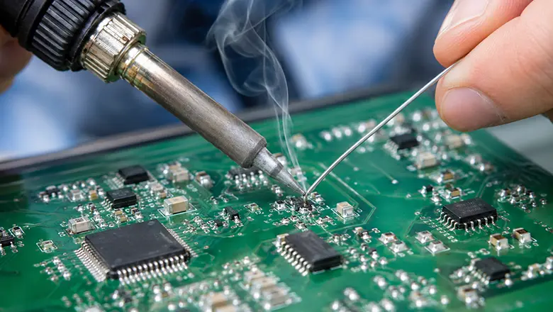
When selecting the appropriate soldering temperature, professionals must weigh a combination of technical and practical elements. Here are the most crucial factors influencing soldering and why they matter so much for PCB reliability.
1. PCB Material and Copper Thickness
The rates at which a PCB absorbs and dissipates heat are directly related to the board material and weight. FR-4 absorbs heat quickly and retains it; in contrast, aluminum-based or ceramic substrates dissipate heat rapidly. Because these materials do not retain heat well, soldering requires higher temperatures and longer dwell times. Additionally, the copper thickness and layer count of the board influence heat dynamics.
- Thicker copper traces or multiple layers draw heat away from the soldering area, so you may need higher temp or a large iron tip.
- Thin boards or single-sided boards require less heat; avoid setting the temperature too high, as this can cause pads to lift and the board itself to blister or delaminate.
2. Type of Solder and Alloy Composition
There are differences between various types of solder—such as leaded, lead-free, and specialty alloys—each requiring different soldering temperatures and offering distinct characteristics regarding fluidity and “feel” during application.
- Lead-free solders (like SAC305) have high melting points, requiring the soldering iron temperature to be set higher.
- Specialty low-temperature solders—such as bismuth-based low-melting-point alloys—are primarily used for precision repairs. Components that cannot withstand high heat, such as mobile phone motherboards or circuit boards with heat-sensitive plastic connectors, require these low-temperature solders.
3. Component Sensitivity
Electronic components have maximum temperature limits. Sensitive parts—such as precision chips, LED beads, and miniature connectors—require strict temperature control. Operate at the lowest feasible temperatures, combine this with pre-baking using hot air, and precisely regulate the soldering iron temperature to ensure a gradual rise in pin temperature.
4. Soldering Method and Thermal Mass
As three mainstream soldering methods, manual soldering, reflow soldering, and wave soldering differ significantly in their heat transfer mechanisms, temperature field distributions, and the interplay between process windows and PCB assembly; consequently, the specific focus of temperature control varies markedly for each.
- In mass production, for solder joints with high thermal mass, it is advisable to use a high-power soldering iron (≥80W) paired with a chisel or hoof-shaped tip possessing high thermal capacity. This ensures sufficient heat input to promote proper solder flow and wetting, thereby preventing soldering defects caused by inadequate heat.
Key Stages in Soldering Temperature Control for PCB
A successful soldering operation involves more than just heating and cooling. Each stage must be dialed in for the solder alloy, the specific temperature, and the assembly method.
Successful soldering involves more than just temperature regulation; it requires precise adjustments at each stage based on the solder type, set temperature, and assembly method:
- Preheating: Gradually raise the temperature of the entire board to ensure uniform heating; avoid sudden blasts of intense heat that could damage the assembly.
- Soaking: Maintain the temperature within the appropriate range to activate the flux and ensure thermal equilibrium across the heated zones.
- Reflow: The temperature spikes to its peak, exceeding the solder’s melting point, allowing the solder to “spread out” and wet every component lead and pad.
- Cooling: The cooling rate must be moderate; cooling too rapidly creates internal stress within the solder joint, while cooling too slowly affects the solder grain structure and mechanical strength.
Solder Melting Points and Typical Iron Temperatures
| Solder Alloy | Melting Point (°C) | Typical Iron Tip (°C) |
| Tin/Lead 63/37 | 183 | 310–320 |
| Lead-Free SAC305 | 217–221 | 350–370 |
| Tin/Lead 60/40 | 190 | 310–330 |
| Bismuth/Tin Alloy | 138 | 200–230 |
Soldering Techniques for Optimal Results
Mastering the soldering process relies not merely on the precise setting of temperature parameters, but rather on the deep integration of operational skills and process details. The following core methods and advanced techniques—validated through extensive production practice—are designed to ensure that every solder joint achieves a consistently high level of quality and reliability.
- Tin your iron tip before starting, ensuring excellent heat transfer and preventing oxidation.
- Apply flux generously to all joints, especially with lead-free solder—this ensures that the solder flows well across the surface of the pcb.
- Feed solder wire to both the iron and the joint for even distribution of molten solder.
- Use hot air rework stations for removing SMD components needing uniform heat across all pins. Hot air also works for dense pin headers and connectors when traditional soldering iron contact is impractical.
- Touch up with a fine soldering tip when working with tiny pads or component leads.
Advanced Tips:
- Solder paste should be used for Surface Mount Technology (SMT) processes; the flux contained within the paste ensures smooth solder melting and uniform wetting during reflow soldering.
- For pads with high thermal mass, it is advisable to locally preheat the soldering area with a soldering iron before applying solder wire, thereby ensuring adequate solder flow.
- When soldering pads with thermal relief or large copper pour areas, the set temperature may be temporarily increased slightly (for a few seconds) and then returned to the standard setting once the specific joint is soldered.
Common Soldering Mistakes & How to Avoid Them

- Cold Solder Joint If the soldering temperature is too low or the solder application is uneven, the resulting solder joints appear dull and porous with insufficient bonding strength, easily leading to poor contact or premature failure. Countermeasure: Clean the PCB pads and adjust the temperature to the appropriate level.
- Overheating Components If the soldering iron tip remains in contact for too long or the temperature is set too high, it can cause oxidation of the component leads, melting of the plastic packaging, or even damage to the internal chip. Countermeasure: Minimize contact time by ensuring movements are “fast, accurate, and steady,” and match the soldering iron’s power and temperature to the specific requirements.
- Insufficient Solder or Excessive Solder Insufficient solder fails to fully cover the pad, resulting in cold joints or weak connections; conversely, excessive solder can lead to spherical accumulations (solder beads) or bridging between adjacent solder joints. Countermeasure: Strictly control the amount and duration of solder feed to ensure both electrical connectivity and mechanical strength.
- Not Using Flux or Using Old Flux Flux must be activated within a specific temperature range to remove oxides from metal surfaces, reduce solder surface tension, and promote wetting. Countermeasure: Always use fresh flux before critical soldering operations and verify that its activation temperature matches the current process.
Risks of Incorrect Soldering Temperature to PCB Inner Layers
Consistently using improper soldering temperature poses serious risks:
- Thermal delamination: Repeated exposure to high temperature separates the board’s layers, breaking critical connections.
- Popcorning: Moisture in components expands rapidly at high temp, often exploding plastic packages.
- Pad lifting and trace damage: Overheated pads can lift off the surface of the pcb, requiring complex repair (if it’s even possible).
How to Mitigate Soldering Risks and Maintain PCB Quality
- Use a temperature-controlled soldering station with precise settings for your solder alloy.Whether it’s leaded solder, lead-free solder, or a specialty type, correct and effective temperature control is essential.
- Calibrate your iron tip using a thermometer periodically.Even high-end stations can drift over time.
- Apply the right amount of solder wire and flux to every joint.Don’t be stingy and don’t be wasteful.
Inspect all joints under magnification. Look for smooth, shiny connections without voids or cracks.
Frequently Asked Questions: Soldering Temperature for PCB
Q1: What’s the ideal temperature for hand soldering?
A: For leaded solder, 310–320 °C; for lead-free solder, 340–370 °C. Always check your solder’s datasheet for the required temperature.
Q2: When should I use a higher temperature?
A: On thick copper traces, planes, or heavy component leads, a higher temperature may be necessary to achieve complete melt and wetting.
Q3: Can I harm a circuit board by using lower temperature?
A: Yes, if the temperature is too low, solder won’t melt properly, leading to unreliable joints.
Q4: How does flux improve my soldering results?
A: Flux removes oxides and contaminants, ensuring the solder flows smoothly and wets every surface.
Q5: Why is temperature control essential in delicate electronics?
A: Without temperature control, sensitive components can be irreparably damaged, resulting in a failed board.
Best Practices for Safe and Effective Soldering
- Always use proper temperature control equipment: Blind soldering due to lack of experience leads to fluctuating temperatures, unreliable solder joint quality, and process risks.
- Invest in a higher wattage soldering iron: Ensure sufficient power for stable heat delivery to the solder joint, preventing mid-process rejects.
- Maintain your soldering iron tip: Keep the tip tinned and clean; promptly replace tips that have developed oxidation pits or severe wear.
- Use the appropriate solder and flux combination: Match the flux to the specific solder type—whether leaded, lead-free, or a special alloy.
Conclusion: Perfecting Your Soldering Temperature for PCB
The LHD TECH team believes that achieving expert-level craftsmanship in PCB assembly requires a profound understanding of the nuances of soldering temperatures; the precise balance between temp settings, solder type, flux compatibility, and operational technique directly determines whether the final product is durable or prone to premature failure. Consequently, we regard temperature control across the entire soldering process—from preheating to cooling—as the cornerstone of our manufacturing, meticulously managing every stage to ensure the functional integrity and reliability of every circuit board.
Your Checklist for Good Soldering
- Select the appropriate soldering temperature based on the PCB type, component lead material, and solder alloy to ensure an optimal match.
- Maintain your soldering iron tip diligently and keep it well-tinned to ensure efficient heat transfer and the formation of stable solder joints.
- Use a sufficient amount of flux to remove oxides and allow the solder to spread and thoroughly wet the surface, ensuring a reliable solder joint.
- Always ensure you’re using a temperature-controlled soldering station and monitor the temperature of the tip for accurate, repeatable results—especially when working with lead-free solder or delicate electronics.
- Adjust your temperature settings to suit the job: use a higher temperature for large thermal masses or thick copper, but a lower temperature for sensitive ICs or connectors.
Why the Right Temperature is Non-Negotiable
Setting your equipment to the correct temperature means more than just knowing the melting point of the solder alloy. You must factor in the board structure, component sensitivity, and the thermal conductivity of each material. Failing to do so can result in a host of issues:
- Cold solder joint from insufficient heat (the solder never flows fully)
- Lifted pcb pads and trace damage from overheating
- Unreliable connections that might collapse after thermal cycling in the field
Practical Example: Soldering Heavy-Gauge Component Leads
When soldering a large inductor or transformer pin on a through-hole PCB, use a chisel iron tip and a higher wattage soldering iron. Preheat the joint, apply ample flux, and increase your iron’s set temperature by 20–30 degrees celsius beyond your normal temp for regular joints. This ensures that the solder wire melts and flows properly around every surface of the component lead and pcb pad, producing a robust joint.
The Role of Modern Equipment
Today’s advanced soldering stations offer precise temperature control, instant recovery, and programmable temperature profiles. These features help ensure not only safer soldering operations, but also far better yields—especially as PCBs become denser and more complex. For wave soldering, a calibrated and well-maintained solder pot is essential, and for SMD, programmable reflow ovens provide the exact temperature your solder paste or alloy demands, every time.
Essential Safety, Inspection, and Final Testing Steps
- Always inspect your solder joints under magnification. Look for smooth, shiny surfaces with concave meniscus (especially critical with leaded solder), and ensure no dull, crystalline, or balling effects remain.
- Test your boards thoroughly with both power-on and continuity checks. This is especially vital after major rework or when adapting to a new soldering technique or solder type.
Final Thoughts
There’s no shortcut to high-quality solder joints and PCB reliability:
- Choosing the right solder, soldering iron temperature, and flux for the job makes a dramatic difference.
- Understand both the required temperature for the solder and the practical needs of your circuit board design.
- Adopt, maintain, and constantly improve proper temperature control in every aspect—from setting the soldering iron right up to final inspection.
- Study and follow industry standards. Reference IPC guidelines for every assembly and process question.
Whether you’re performing hand soldering, working with lead-free, or managing large wave soldering production lines, the foundation is always the same: selecting the appropriate soldering temperature, controlling it carefully, and verifying each solder joint’s quality. Consistency, precision, and respect for the science of soldering ensure that the solder melts at precisely the right moment for robust, long-lasting, and professional PCBs.