Try soldering a wire onto a pin spaced 0.4mm from its neighbor, and you will understand right away why breakout boards exist.
Modern chips pack hundreds of connections into packages barely bigger than a grain of rice. It is fantastic for miniaturization but a nightmare to test or prototype with them by hand. How do you connect and test a component whose pins are too small or too closely spaced?
A breakout board solves the exact problem. It mounts the component on a small PCB and routes the connections to large standard headers you can actually work with. It may also add useful supporting circuitry such as voltage regulation, signal conversion, pull-up resistors, LEDs, or communication connectors.
This guide covers what a breakout board is, how it works, the different types, and how to pick the right one for your project.
What Is a Breakout Board?
A breakout board is a specialized, purpose-built PCB whose job is to take a component’s tiny packed pins and spread them out into something you can use.
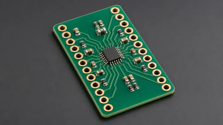
Consider a tiny surface-mount sensor with contacts that cannot be inserted into a breadboard. A breakout board can mount that sensor and route its pins to a row of 0.1-inch headers. This makes it compatible with common prototyping hardware and accepts a jumper wire without any fuss.
A breakout board may expose a component’s power, ground, digital I/O, analog inputs, communication interfaces, or other pins through standard headers, solder pads, terminal blocks, or connectors. That fanning-out process gives the board the name of “breakout” because it breaks out the pins into a format people can work with.
For a closer look at how these layers and connections come together on a board, see our breakdown of circuit card assembly components.
How Does a Breakout Board Work?
A breakout board creates a physical and electrical bridge between a compact component and the rest of the circuit. It turns that high-density component into a plug-and-play component. The process flows in the following order:
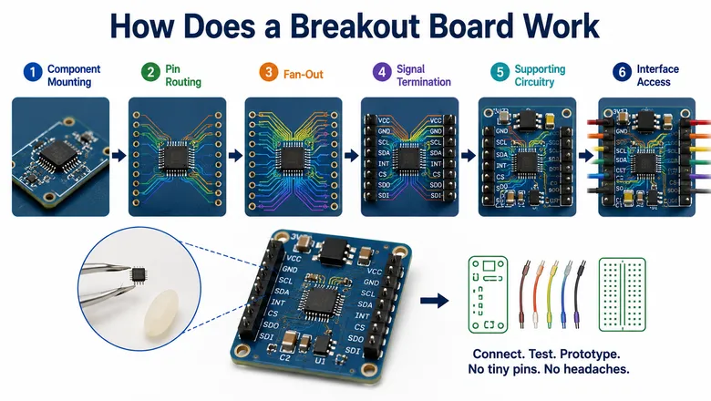
- Component Mounting: The chip/sensor/module is soldered onto the board using precision equipment.
- Pin Routing: Each connection on the component gets traced individually to its own dedicated pad on the board.
- Fan-Out: Traces spread outward from the packed component and gradually widen in spacing as they move toward the board’s edges.
- Signal Termination: Pins land on standard-pitch headers, through-hole pads, or connectors. They are spaced wide enough for jumper wires or breadboard use.
- Supporting Circuitry: Passive components (decoupling capacitors or voltage regulators) are added near power pins to keep the component stable.
- Interface Access: Engineers connect and test through the labeled headers. They never have to touch the component’s original pins.
All that routing and fanning out happens so nobody has to solder a wire to something smaller than a grain of sand.
Key Components/Features of a Breakout Board
Breakout boards have some consistent set of building blocks that make them functional.
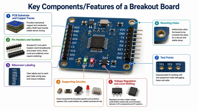
PCB Substrate and Copper Traces
The board provides the physical structure and conductive paths needed to connect the target component to external interfaces. More complex breakout boards may include multiple layers to accommodate dense routing.
Pin Headers and Sockets
Most breakout boards use standard 0.1-inch pitch pin headers or sockets, which match the spacing found on breadboards and jumper wire connectors. Some boards come with headers pre-soldered, while others require you to solder them yourself or leave them out entirely. Check this point before buying.
Silkscreen Labeling
Every functional pin (VCC, GND, SDA, SCL, TX, RX, and similar) is printed on the board next to its corresponding pad. This labeling removes the need to cross-reference a datasheet every time you wire something up and cuts down on wiring mistakes.
Supporting Circuitry
You may see boards include small passive components alongside the main chip, such as decoupling capacitors, pull-up resistors, voltage regulators, status LEDs, crystal oscillators, etc. These parts help stabilize power delivery and protect the component from voltage spikes.
Voltage Regulation and Level Shifting
Since many components are sensitive to voltage, breakout boards include an onboard regulator to accept a range of input voltages and output a stable/safe supply. Some also add level shifters so that a 3.3V component communicates safely with 5V systems like Arduino.
Mounting Holes
Small drilled holes near the board’s edges allow it to be secured with screws. This keeps the board stable when integrated into an enclosure or a larger PCB assembly and prevents accidental disconnections.
Test Points
Some boards include exposed metal pads for probing with a multimeter or oscilloscope. These test points make it easier to check voltages or signal behavior without risking damage to the component underneath.
6 Reasons to Use Breakout Boards
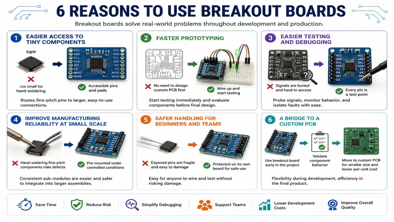
Breakout boards do more than just make components easier to handle. They solve real-world problems that come up throughout development and production.
Easier Access to Tiny Components
Many modern components are built for automated surface-mount assembly and have pins with no space for hand-soldering. A breakout board mounts these components on a larger PCB and routes their connections to accessible pins or pads. This is crucial for packages like TQFP, where tight pin pitch makes hand-soldering or breadboard use nearly impossible without a breakout board.
Faster Prototyping
Engineers can wire up a ready-made breakout board and start testing almost immediately. There is no need to design a full custom PCB around an untested component. This cuts out a significant chunk of upfront layout work, which is useful when evaluating components before committing to a final design.
Easier Testing and Debugging
Signals are buried and inaccessible on a compact production board. A breakout board exposes every pin as a reachable test point. Engineers can probe signals and isolate faults with standard test equipment.
Improve Manufacturing Reliability at Small Scale
Hand-soldering fine-pitch components introduces a real risk of defects, especially in low-volume runs. Pre-mounting them onto breakout boards under controlled manufacturing conditions produces dependable sub-modules that are easier and safer to integrate into a larger assembly.
Safer Handling for Beginners and Teams
The fragile component is permanently mounted and protected on its own board. So, anyone working with it can wire and test it without risking damage to exposed pins from repeated handling.
A Bridge to a Custom PCB
Breakout boards are valuable early in a project’s life. After it helps validate the component’s behavior, engineers can move it into a custom PCB.
Common Types of Breakout Boards
There is a wide range of breakout boards in the market. Many are purpose-built for different applications. Some of the common types are:
Sensor Breakout Boards
They provide access to sensors for measuring properties such as:
- Temperature
- Pressure
- Humidity
- Acceleration
- Magnetic fields
- Light
- Gas concentration
A sensor breakout may expose digital interfaces such as I²C or SPI, analog outputs, or both.
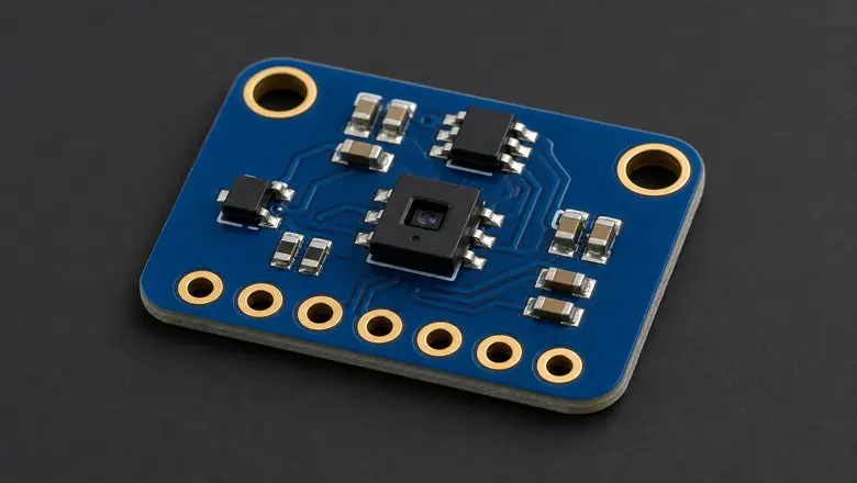
IC and Microcontroller Breakout Boards
These boards make the pins of a small integrated circuit or microcontroller easier to access. They may expose GPIO, communication interfaces, power connections, and programming interfaces.
Some boards include only the basic connections, while others add features such as buttons, LEDs, clock circuits, or power regulation.
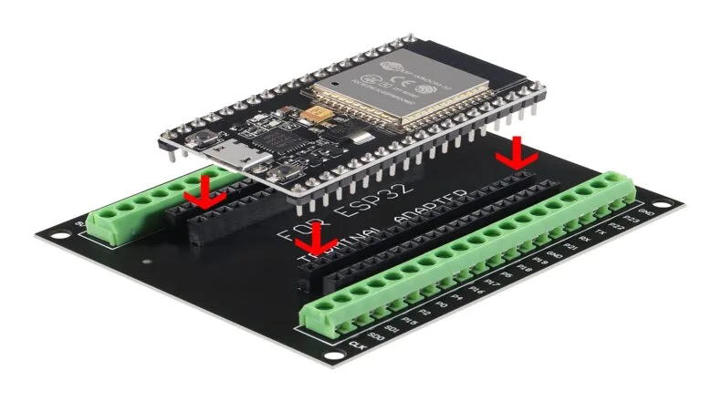
Communication & RF Modules
These boards provide access to communication technologies such as USB, UART, RS-232, RS-485, CAN, I²C, SPI, Bluetooth, Wi-Fi, and cellular connectivity.
A communication breakout may also include the required transceiver, connector, antenna interface, or signal conversion circuitry.
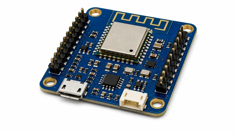
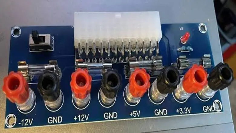
Power Breakout Boards
These boards make it easier to distribute, monitor, or convert power. They may include voltage regulators, terminal blocks, fuses, switches, or multiple output connections. They are useful when a project needs to distribute power to several components or convert an input voltage into one or more regulated outputs.
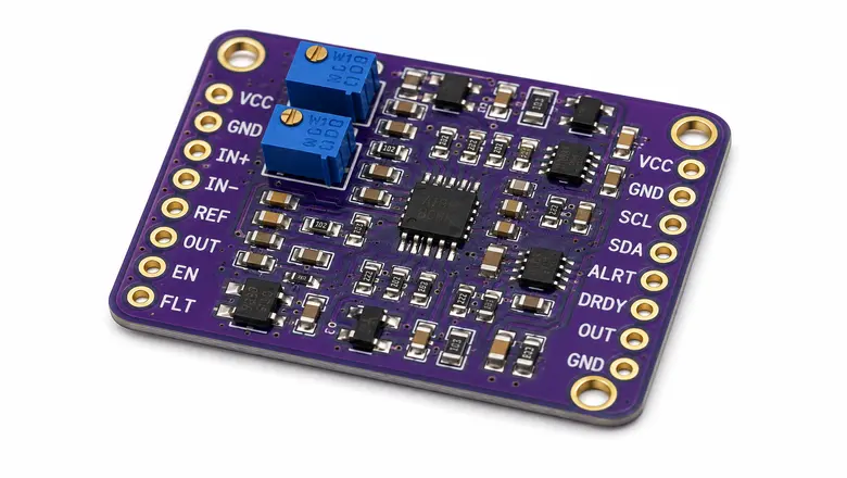
Signal Conditioning Breakout Boards
Signal conditioning boards modify electrical signals so they can be read or used by another circuit. They may provide functions such as amplification, filtering, isolation, voltage conversion, or analog-to-digital conversion.
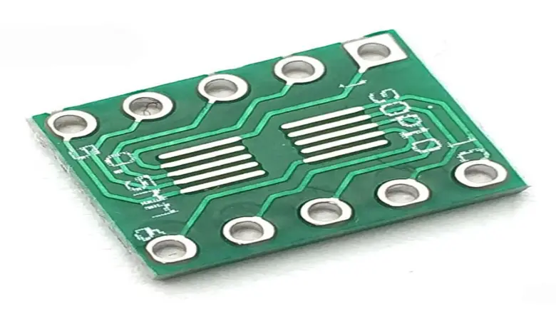
IC Package Adapter Boards
IC package adapter boards convert one physical package or pin arrangement into another format that is easier to prototype with. For example, they may mount a small surface-mount IC and route its pins to a standard through-hole layout.
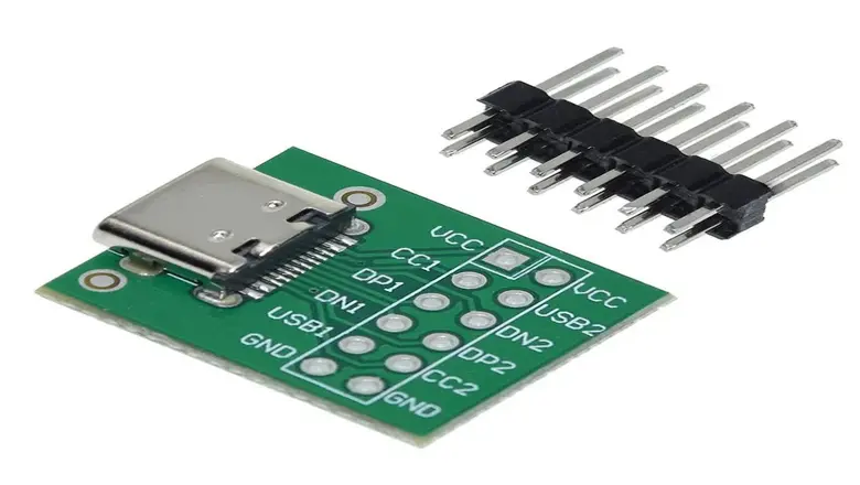
Connector Breakout Boards
Connector breakout boards convert specialized connectors into individual and more accessible pins or terminals. Common examples include boards for USB, HDMI, FFC/FPC, JST, and other connectors.
Application-Specific Breakout Boards
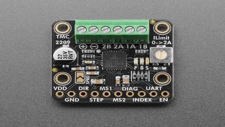
Some breakout boards are meant for a particular application rather than a single component or interface. Examples include boards for motor control, battery monitoring, GPS, audio processing, data logging, and other specialized functions.
Key Considerations When Selecting a Breakout Board
When there are multiple types of breakout boards, choosing the right one matters. Check the following before choosing one:
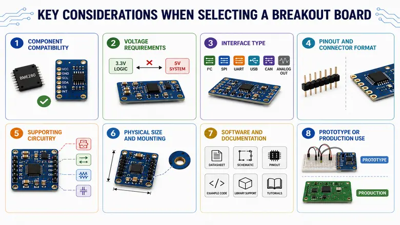
- Component Compatibility: Make sure the board uses the exact component you need. Check the specific model, revision, operating range, and supported features.
- Voltage Requirements: Confirm the board’s input voltage and logic levels. A 3.3 V board may not work directly with a 5 V system.
- Interface Type: Check that it supports the interface your project needs, such as I²C, SPI, UART, USB, CAN, or analog output.
- Pinout and Connector Format: Make sure the pins and connectors suit your setup. Standard 0.1-inch headers work well with breadboards, but castellated edges are useful for direct PCB integration.
- Supporting Circuitry: Check for built-in features such as voltage regulators, level shifters, pull-up resistors, and connectors that could simplify your design.
- Physical Size and Mounting: Confirm that the board fits your available space and that its mounting holes/connectors and component height work with your design.
- Software and Documentation: Look for a clear datasheet, schematic, pinout, example code, and library support to avoid unnecessary development headaches.
- Prototype or Production Use: Breakout boards are excellent for testing, but a custom PCB is usually a better choice for compact and high-volume production designs.
Real-World Applications of Breakout Boards
Breakout boards are used across the electronics development process.
Robotics
Robotics projects use breakout boards for sensors, motor controllers, inertial measurement units, distance sensors, and wireless communication modules.
IoT Devices
Engineers can test environmental sensors, wireless connectivity, GPS, and other functions much faster before developing a custom IoT PCB.
Wearable Electronics
Small sensors and specialized ICs require compact packaging. Breakout boards allow engineers to test these components before integrating them into a wearable device.
Industrial Prototyping
Engineers can evaluate sensors, communication interfaces, and control components without committing to a production PCB right away.
Education and Maker Projects
Breakout boards make advanced components easier to use with development boards and breadboards. They are common in electronics education and maker projects.
Product Development and Testing
A development team may use breakout boards to evaluate several components and compare their performance before selecting one for the final product.
Breakout Board vs. Breadboard vs. Custom PCB
Each of these tools plays a different role in the development process. Many times, they are used together.
| Aspect | Breakout Board | Breadboard | Custom PCB |
| Purpose | Exposes a single component’s pins | General-purpose circuit assembly | Complete, dedicated circuit design |
| Soldering | Component pre-soldered by manufacturer | No soldering required | Requires soldering |
| Connections | Fixed headers/pads for the component | Insertable, reusable holes | Permanent copper traces |
| Best for | Working with fine-pitch/SMD parts | Fast, temporary testing | Final products, mass production |
| Reliability | Stable, solid connections | Prone to loose contacts over time | Reliable and permanent |
| Signal performance | Good | Poor at high speed/frequency | Best |
| Customization | Fixed to one component | Fully flexible layout | Fully customized to project |
| Reusability | Reusable across projects | Reusable across projects | Project-specific (not reusable) |
| Cost (low volume) | Low to moderate | Very low | High (design + fabrication) |
| Cost (high volume) | Not cost-effective at scale | Not applicable | Most cost-effective |
| Typical stage of use | Early testing, evaluation | Rapid prototyping | Final production |
Conclusion
A breakout board makes modern electronic devices development a lot easier. It exposes tiny pins and specialized interfaces through more accessible connections. It helps save time during testing sensors, evaluating communication modules, preparing a component for integration into a custom PCB, and more. To wrap up, these boards act as the bridge between the component and the rest of your project.
FAQs
What is the difference between a shield and a breakout board?
A breakout board exposes the pins or connections of a component to make it easier to access and test. A shield is attached directly to a specific development board, such as an Arduino, and adds a complete function or feature.
Why is it called a breakout board?
It is called a breakout board because it “breaks out” difficult-to-access connections from a compact component or connector and routes them to larger and more accessible pins/pads/ headers for easier testing and prototyping.