
Introduction: Rectifiers, Diodes & the Need for DC
Alternating current (AC) brings energy from power plants to our homes and factories, but direct current (DC) voltage powers nearly every electronic device, microprocessor, and control system. The rectifier—an electronic circuit built mainly of diodes—enables this crucial AC to DC conversion. Whether you’re designing a robust power supply, an electric vehicle charger, or a tiny sensor module, understanding the full wave rectifier is fundamental.
A rectifier circuit uses diodes to control current flow, delivering dc voltage across the load. Of all rectifier types, the full wave rectifier—including its bridge rectifier variant—is the most effective, versatile, and widely adopted in both consumer and industrial electronics.
What is a Rectifier?

A rectifier is a device or circuit that converts AC voltage (which alternates between positive and negative values) into a pulsating DC voltage. The essential element is the diode, which only allows current to flow in one direction. With the clever arrangement of diodes, engineers can convert the AC input—a sine wave—into a DC output across a load resistor.
Rectifiers are everywhere:
- In the adapter for your phone
- Inside every computer’s power supply
- In all battery chargers, from electric vehicles to AA cell chargers
- Powering sensors, LED lights, and analog circuits with stable DC
Key Points:
- Rectifier circuits can be classified into half-wave and full-wave rectifier
- The rectifier and bridge rectifier are fundamental parts of all power electronics.
- Voltage conversion is the rectifier’s chief function.
Types of Rectifier Circuits: Half Wave and Full Wave Rectifier
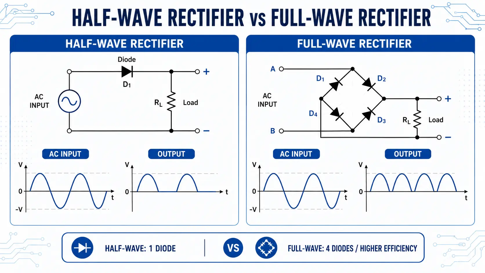
There are several types of rectifier circuits:
Half Wave Rectifier
A half-wave rectifier uses one diode. It only utilizes one half of the AC input, either the positive or negative half cycle. Current only flows through the load during one half of the AC cycle; the other half is blocked.
- Pros:Simplicity, cost-effective
- Cons:Poor efficiency, high ripple voltage, not ideal for most power applications
Half-Wave Rectifier Circuit
A basic half-wave rectifier circuit has an AC input, a diode, and a load resistor. The diode will be forward biased during the positive half of the input, allowing current flow and developing a voltage across the load resistor. During the negative half of the AC cycle, the diode blocks current, and there’s no output voltage.
Full Wave Rectifier
Unlike a half‑wave design, a full‑wave rectifier actually puts both the positive and negative halves of the AC waveform to work. So instead of wasting half the cycle, the load gets current during both swings of the input sine wave which not only gives you a noticeable efficiency boost, but also helps flatten out the ripple on the output side.
There are two standard ways to build one. The first is the center‑tapped full‑wave rectifier, which needs a transformer with a center tap and a pair of diodes.
The second is the bridge rectifier, which uses four diodes wired in a bridge configuration – and the nice thing is, it doesn’t require that center tap at all. Whichever topology you go with, the current through the load resistor ends up flowing in the same direction for both halves of the AC cycle, so you get a steady polarity without any flip‑flop.
Full Wave Rectifier: Definition & Working Principle

In power electronics, a full‑wave rectifier is a diode‑based circuit that takes an AC input – both its positive and negative alternations – and turns it into a unipolar DC output. Unlike its half‑wave cousin, which only grabs one half of the cycle and throws the rest away, the full‑wave design makes use of the entire waveform, so you get a much more useful result.
Let’s break down what that really means in practice:
- Instead of just clipping off half the waveform, a full‑wave rectifier actively conducts during both halves of the AC cycle, delivering a pulsating DC that never goes to zero between peaks.
- This approach gives you two big wins: more current gets pushed through the load, the average output voltage climbs higher, and the remaining ripple is noticeably smaller than what you’d see with a half‑wave circuit.
- Another interesting side effect – the ripple frequency at the output doubles relative to the input AC. For instance, if you’re feeding it with a 50 Hz mains supply, the output will have a 100 Hz ripple component, which makes it a lot easier to filter out with a simple capacitor.
- So in short, the full‑wave rectifier isn’t just a marginal improvement – it’s the go‑to choice whenever you need a practical, efficient DC source from an AC supply, and it forms the foundation for most linear power supplies you’ll come across.
Full-Wave Rectification
The aim is to convert alternating current to a direct current signal by using two diode or four diodes in clever circuits. In each case, the circuits ensure that no matter the AC polarity, the voltage across the load is always in the same direction.
Rectification efficiency for full wave rectifiers is 81.2%, as opposed to ~40.6% for a half-wave variant.
Full Wave Rectifier Circuit Diagrams: Center Tap & Bridge
Full wave rectifiers come in two major circuit designs: center tapped full wave rectifier and the bridge rectifier circuit.
Center Tapped Full Wave Rectifier
- Transformers with a center tap supply equal and opposite voltages on either side of the tap (called the secondary winding).
- The diodes are arranged so that during the positive half cycle, one diode conducts and during the negative half cycle, the other diode conducts.
- Output voltage is developed across the load resistor in the same direction during both halves of the AC input.
Example Circuit:
- Secondary winding of the transformer has end A, center tap (C), and end B.
- During positive half cycle (A is positive relative to C): Diode 1 is forward biased; diode 2 is reverse biased.
- During negative half cycle (B is positive relative to C): Diode 2 conducts; diode 1 blocks.
Bridge Rectifier Circuit
The bridge rectifier (known as a bridge rectifier circuit or full-bridge rectifier) uses four diodes arranged in a bridge configuration. Here, no center tap on the transformer is needed.
- During the positive half of the input: Current flows through two diodes and the load in one direction.
- During the negative half: The other two diodes conduct, maintaining the same current direction across the load.
Waveform Analysis
Whether using a center tapped full wave rectifier or bridge arrangement, the output waveform is a series of positive pulses (pulsating dc) at double the input frequency.
Components of Full Wave Rectifier Circuits
The performance and reliability of a rectifier circuit are determined by the quality and characteristics of its core components:
Diode
- The diode is the active switching element.
- For bridge rectifier circuits, four diodes are used; for center tapped, two diodes.
- Silicon diodes(such as the 1N4007) are common, but Schottky diodes may be used for high-frequency applications due to their lower voltage drop.
Transformer
- Steps down (or up) the AC voltage and isolates the circuit.
- Center tap required for the center tapped full wave rectifier, while the bridge rectifier can use a standard transformer without a center tap.
- The secondary winding of the transformer supplies the AC voltage to be rectified. In the center-tapped version, it is divided into two halves—each half of the secondary winding corresponds to one diode’s conduction period.
Load Resistor
- The load resistor represents the circuit or device being powered by the rectified DC output.
- The DC voltage appears across the load resistor after rectification and filtering.
Filter Capacitor (for smoothing)
- A filter capacitor is often connected in parallel with the load resistor to smooth the pulsating DC output, reducing ripple voltage and providing more stable DC voltage for sensitive electronic circuits.
Quick Checklist for Building a Full Wave Rectifier Circuit
- Choose diodes rated above your maximum expected AC voltage and current.
- Ensure the transformer’s secondary voltage suits your DC output requirements.
- For center-tapped designs, confirm the transformer’s secondary is evenly split.
- Pick a filter capacitor that can handle at least 1.5× the expected DC output voltage.
Center Tapped Full Wave Rectifier: Operation & Example
The center tapped full wave rectifier is a classic rectifier circuit for educational and light-duty purposes.
How it Works
- The transformer’s secondary winding has a center tap, dividing the winding into two equal halves.
- During the positive half cycle of the AC input, one diode is forward-biased and conducts, allowing current to flow through the load in one direction.
- During the negative half cycle, the other diode conducts, again sending current through the load in the same direction.
- Thus, both the positive half and negative half of the AC input are transformed into pulsating DC voltage across the load.
Example Walkthrough
Suppose the transformer’s secondary produces 24V AC center-tapped, providing +12V and −12V relative to the center tap:
| Half Cycle | End A Voltage | End B Voltage | D1 Status | D2 Status | Current Flow |
| Positive half | +12V | −12V | Conducts | Blocks | Forward through RL |
| Negative half | −12V | +12V | Blocks | Conducts | Forward through RL |
In each half, one of the two diode pair conducts and DC output is always in the same direction across the load resistor.
Bridge Rectifier Circuit: Construction, Waveform & Advantages
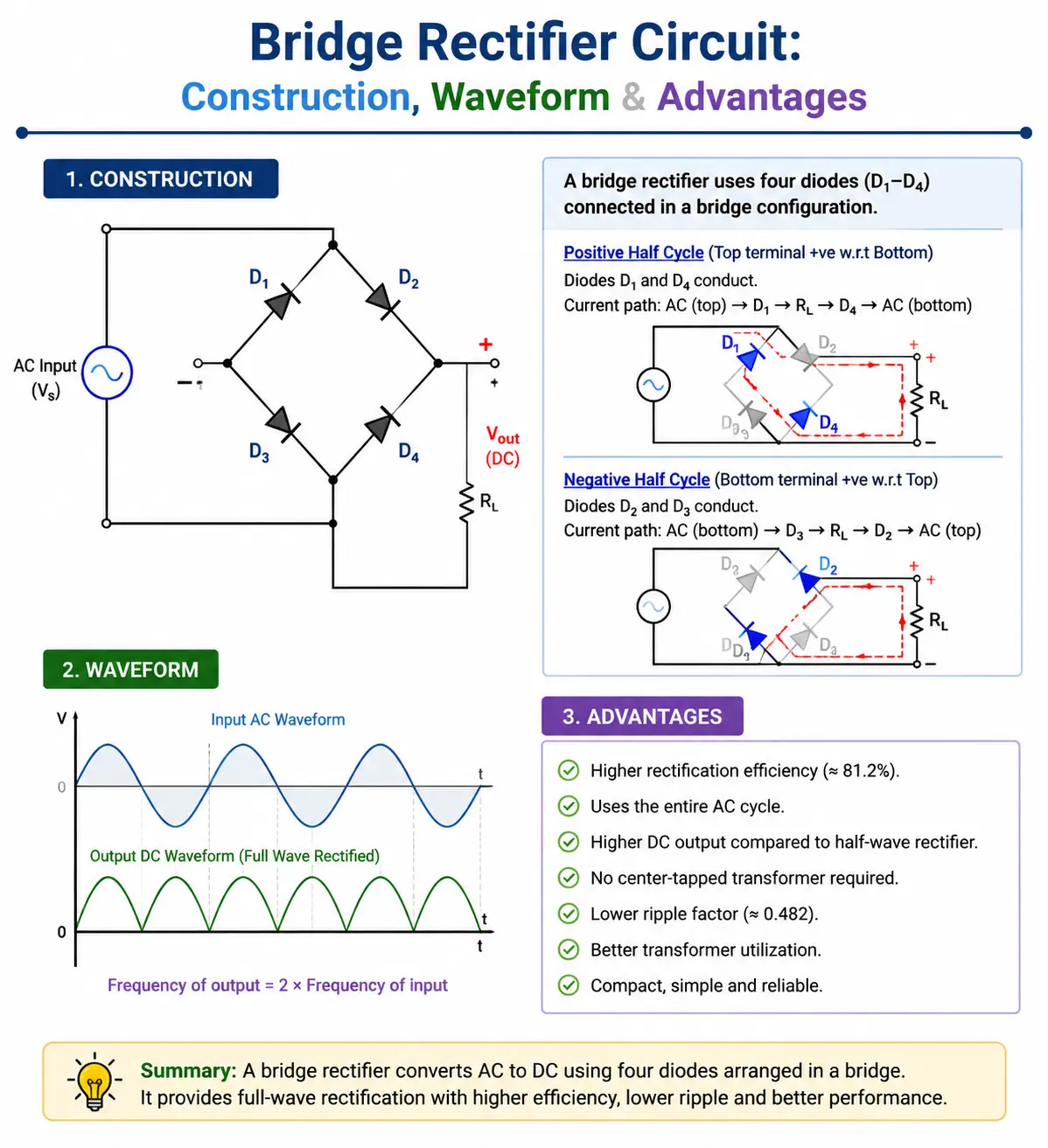
The bridge rectifier circuit is the most popular full wave rectifier due to its superior performance and ease of use.
Bridge Configuration
- Uses four diodes arranged in a bridge circuit, allowing full-wave rectification without requiring a center-tapped transformer.
- Two diodes conduct during each half cycle—always directing current flow the same way through the load.
Working Principle
- Positive half of the AC cycle: Diodes D1 and D2 are forward biased and conduct current. D3 and D4 are reverse biased.
- Negative half cycle: D3 and D4 conduct, D1 and D2 block.
- Current always flows in the same direction across the load, resulting in a dc output.
Output Waveform
The output waveform from a bridge rectifier is similar to that of a center-tapped full wave rectifier—pulsating DC with double the input frequency and more continuous current flow than a half-wave rectifier.
Advantages Over Center-tapped Rectifiers
- No need for special transformers—just a standard secondary winding.
- Lower peak inverse voltage requirement on each diode (Vm instead of 2Vm).
- Transformer utilization factor is higher in bridge rectifier designs, maximizing value.
- More compact and economical for most power applications.
Rectifier Output, Waveform Analysis, and Ripple Voltage
What Does “Pulsating DC” Mean?
Even after full wave rectification, the output is still not pure DC—it has ripples. The output waveform rises and falls twice per AC input cycle. This pulsating DC can cause issues in devices sensitive to voltage fluctuation.
Analyzing Ripple Voltage
- Ripple voltage (the residual AC in the rectifier output) can cause buzzing in audio equipment and malfunction in digital circuits.
- Formula: For a full wave rectifier with a simple capacitor filter: Vripple = Iload / (f × C) where Iload is the load current (across the load resistor), f is the ripple frequency (twice AC input frequency), and C is the capacitance.
- Ripple can be reduced dramatically by increasing C or using improved filter circuits (LC, RC, etc.).
Output Voltage Characteristics
- Theoretical output voltage for a bridge rectifier: Vdc = (2 × Vm) / π, where Vm is the peak value from the transformer’s secondary
- Practical output will be a bit less due to the voltage drop across the conducting diodes (typically 0.7V per silicon diode).
Waveform Comparison Table
| Rectifier Type | Output Waveform | Ripple Frequency |
| Half-wave rectifier | Pulses once per AC cycle | f (input freq.) |
| Full wave rectifier | Pulses twice per AC cycle | 2f |
| Bridge rectifier | Same as full wave, no center tap needed | 2f |
Full Wave Rectifier Formulas: Output Voltage, Ripple & Efficiency
Knowing key formulas allows accurate rectifier and circuit design.
Key Formulas
Output voltage (Vdc): For both full wave bridge rectifier and center-tapped full wave rectifier, Vdc = (2 × Vm) / π where Vm is the peak secondary winding voltage.
RMS output voltage: Vrms = Vm / √2
Peak Inverse Voltage (PIV):
Center tap: 2Vm (each diode)
Bridge rectifier: Vm (each diode)
Rectifier Efficiency (η):
Full wave rectifiers is 81.2%
Half-wave only about 40.6%
Ripple Factor (γ):
Full wave: 0.482
Half-wave: 1.21
Form Factor: Vrms / Vdc = 1.11
Why Use a Full Wave Rectifier vs Half Wave Rectifier?
Compared to a Half-Wave Rectifier
| Feature | Half Wave | Full Wave / Bridge Rectifier |
| Utilizes entire input? | No, only one half | Yes, both positive and negative |
| Average output voltage | Low | High |
| Output waveform | Gappy, high ripple | Smoother, less ripple |
| Transformer utilization | Poor | Excellent (especially bridge) |
| Ripple voltage | High | Lower |
| Output frequency | Same as AC input | Twice AC input |
| Power supplies use? | Rare | Always |
Bottom Line: A full wave rectifier circuit is always preferred for reliable, efficient, and high-performance DC power conversion, especially in all modern power electronics.
Tips for Designing Rectifier Circuits
- Always account for diode loss. Each conducting diode introduces a voltage drop (usually 0.7V for silicon). In a bridge configuration, consider the series drop of two diodes per half-cycle.
- Use larger filter capacitors for lower ripple voltage, but consider surge inrush current at turn-on.
- Match diode PIV to your peak transformer secondary winding voltage. Remember, in a center-tapped full wave rectifier, each diode must withstand the full secondary winding voltage during its blocking period.
- Choose the right transformer. For center-tapped designs, ensure perfect symmetry in the secondary winding.
- Test output voltage under real loads, as excessive or insufficient load can reveal design weaknesses.
- For high output current, use diodes with adequate current ratings or arrange diodes in parallel (with resistors for current sharing).
Full Wave Rectifier with Smoothing Capacitor
When you add a smoothing capacitor to the output of a full‑wave rectifier, the whole game changes. That pulsating DC – the one that jumps up and down with every half‑cycle – gets tamed into something that looks almost like a steady DC line, which is exactly what you need if you’re powering anything sensitive, like audio gear or microcontroller circuits.
- The rectifier itself – whether it’s a center‑tapped or bridge type – only gives you a unidirectional but still rippling output. It’s DC in name, but it’s far from flat.
- That’s where the filter capacitor steps in. It charges up quickly to nearly the peak voltage of the AC waveform during each cycle, and then, between those charging pulses, it gradually discharges through the load. The discharge rate depends on the load current and the capacitor size – if the RC time constant is long enough, the voltage doesn’t drop much before the next pulse comes along.
- The end result? The combination of a full‑wave rectifier and a smoothing capacitor cuts the ripple down to a fraction of what it was, giving you a clean, stable DC voltage that stays within a narrow range. That’s why this setup is the backbone of almost every linear power supply you’ll find in practical electronics.
Application Examples: EV Charging, Power Supplies, and More
Electric Vehicle Charger (EV):
- The bridge rectifier circuit in EV chargers converts the high-voltage AC input from the grid into DC voltage for charging batteries.
- The rectifier circuit must handle large currents, and the bridge configuration of four diodes ensures efficient rectification while withstanding voltage surges and fluctuations.
- Transformer isolation is crucial for safety, while robust filter capacitors minimize ripple voltage, keeping charging efficient and preventing battery damage.
Power Supplies for Electronics:
- Nearly every wall adapter or internal power supply relies on a full wave rectifier or bridge rectifier.
- The output voltage must be reliable with minimal ripple, so designers use a high-quality full-wave bridge rectifier circuit followed by smoothing capacitors.
- In sensitive circuits, a voltage regulator may be added after filtering for near-perfect DC voltage.
UPS (Uninterruptible Power Supply) Circuits:
- Bridge rectifier circuits convert input AC to DC, charging backup batteries while providing power to connected devices.
- The rectifier voltage drop and efficiency determine both recharging speed and DC output reliability.
Audio & Telecommunication Equipment:
- Stable DC is essential for amplifiers, radios, and routers. These all use a bridge rectifier in their power input section.
- Excessive ripple voltage causes audio hum or data errors, so a combination of bridge rectifier, transformer, and filter capacitors provides reliable power.
Industrial Control Panels:
- Industrial automation depends on DC power for relays, logic controllers, and sensors.
- Here, the rectifier used is often a high-capacity bridge rectifier circuit, with each diode oversized to handle surges and transients common in factory environments.
Troubleshooting Common Rectifier Problems
Symptom: No DC output from rectifier
- Possible Causes: Open (burned) diode, failed transformer secondary winding, input AC not present.
- Check: Using a multimeter, verify AC input at the transformer, transformer output voltage, and diode continuity.
Symptom: DC output too low
- Possible Causes: Insufficient secondary winding turns, excessive diode voltage drop, wrong transformer tap, failed capacitor (leakage increases ripple).
- Check: Measure actual transformer secondary voltage, check diode voltage drop during load, confirm filter capacitor value and health.
Symptom: Excessive ripple voltage or output hum
- Possible Causes: Undersized or faulty filter capacitor, excessive load current draining capacitor too quickly, rectifier circuit issue.
- Check: Increase or replace smoothing capacitor, reduce load, inspect for any open or reversed diode in bridge arrangement.
Symptom: Overheating diodes or transformer
- Possible Causes: Diodes with too low current rating, continuous overload, short circuit across load resistor, secondary winding resistance too low, or poor ventilation.
- Check: Confirm diode ratings, test under various loads, add heat sinks or ventilation as needed.
Quick Pro Troubleshooting Table
| Problem | Likely Cause | Diagnostic Step |
| No output voltage | Blown diode, open circuit transformer | Measure AC and DC |
| Low output voltage | Wrong transformer, diode drop too high | Measure each section |
| Ripple voltage higher than expected | Bad capacitor, excessive load | Swap or upgrade cap |
| Excess heat in rectifier | Diode undersized, constant overload | Check diode/capacity |
Conclusion: The Heart of AC to DC Conversion
The full wave rectifier is the gold standard in reliable voltage conversion for all modern power supplies, chargers, and DC-powered electronics. By using either a center tapped full wave rectifier or a bridge rectifier circuit—and supplementing with quality diodes, secondary windings, filter capacitors, and a carefully selected transformer—you can efficiently convert alternating current into steady, usable DC voltage.
Understanding key ideas—how a rectifier circuit operates, how a bridge arrangement with four diodes maximizes current flow, and how filtering and correct transformer selection impact voltage and ripple—empowers you to design, troubleshoot, or upgrade any power circuit, from compact gadgets to industrial machines.
Key Takeaways:
- Rectifiers (especially the full wave rectifier) are essential for converting AC input into DC output for virtually every modern electronic device.
- Compared to a half-wave rectifier, the full wave design achieves better efficiency, higher output voltage, smoother waveform, and significantly lower ripple voltage.
- A bridge rectifier, using four diodes in a bridge configuration, is the most widely used type of rectifier in power electronics for its simplicity and performance.
- Always consider diode ratings, transformer specs, filter capacitance, and actual load conditions in any rectifier circuit design.
- For the smoothest DC output, use a rectifier with a smoothing capacitor matched to the transformer’s secondary winding and your application’s requirements.
A Rectifier is an Electronic Circuit that Converts AC to DC—master its theory, and you master the foundation of all modern electronic power.
Frequently Asked Questions About Full-Wave Rectifiers
1. What Is a Full-Wave Rectifier?
A full-wave rectifier is an electronic circuit that converts both halves of an AC waveform into pulsating DC. It provides a higher average output and better efficiency than a half-wave rectifier.
2. How Does a Full-Wave Rectifier Work?
During each AC half-cycle, different diodes conduct and direct the load current in the same direction. As a result, both halves of the AC input contribute to the DC output.
3. What Are the Two Types of Full-Wave Rectifiers?
The two main types are the center-tapped full-wave rectifier and the bridge rectifier. The center-tapped design uses two diodes, while the bridge design normally uses four.
4. Is a Full-Wave Rectifier the Same as a Bridge Rectifier?
Not exactly. A bridge rectifier is one type of full-wave rectifier, while another type uses a center-tapped transformer and two diodes.
5. How Many Diodes Are Used in a Full-Wave Rectifier?
A center-tapped full-wave rectifier uses two diodes. A full-wave bridge rectifier uses four diodes, with two conducting during each half-cycle.
6. Does a Full-Wave Rectifier Produce Pure DC?
No. Its output is pulsating DC and normally requires a filter capacitor to reduce ripple and produce a smoother DC voltage.
7. What Are the Benefits of a Full-Wave Rectifier?
It uses both halves of the AC cycle, providing higher efficiency, a higher average DC output, and lower ripple than a half-wave rectifier. It also makes the output easier to filter.
8. What Are the Disadvantages of a Full-Wave Rectifier?
A full-wave rectifier requires more diodes or a center-tapped transformer, increasing circuit complexity and cost. Diode forward-voltage drops also reduce the available output voltage.
9. Does a Full-Wave Rectifier Change the Voltage?
Yes. The DC output depends on the AC input voltage, transformer ratio, diode voltage drops, load current, and filtering circuit. A bridge rectifier typically loses approximately two diode forward-voltage drops during conduction.
10. Where Are Full-Wave Rectifiers Used?
Full-wave rectifiers are commonly used in AC-to-DC power supplies, battery chargers, industrial control systems, motor drives, adapters, and electronic equipment requiring stable DC power.