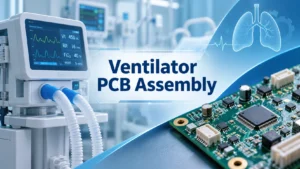

A ventilator may operate for hours while continuously adjusting airflow to support a patient’s breathing. These adjustments depend on a circuit board that processes sensor readings and controls motors and valves. It also activates alarms when the device detects a problem.
Even a small electrical fault can disrupt these functions. For example, an unstable power supply may affect the device’s operation, while inaccurate sensor readings can lead to improper adjustments. A defective solder joint can also interrupt critical electrical connections and compromise performance.
This makes ventilator PCB assembly fall under tighter rules than general electronics. Every stage of this process, whether it’s circuit layout, component selection, inspection, or testing, requires careful attention to reliability and patient safety.
What Is a Ventilator PCB Assembly?
A ventilator PCB assembly (PCBA) is a printed circuit board populated with electronic components that support the ventilator’s monitoring and control functions. It connects the microcontroller or processor with sensors, power circuits, motor drivers, alarm systems, and user interface components.
These functions may be distributed across several interconnected boards depending on the ventilator’s design. For example, a main control board might handle sensor data and ventilation commands, while separate assemblies manage power distribution or the display.
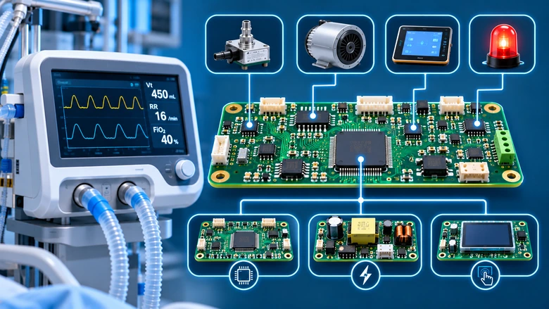
Every connection on these boards carries more risk than it would on consumer electronics. A cracked joint on a pressure sensor line can distort a reading the alarm logic depends on. Similarly, a weak contact on a motor driver can interrupt blower operation. So, the ventilator PCB assembly is judged on the finished, tested board and the records behind it.
How Does a Ventilator PCBA Control Breathing Functions?
A ventilator uses electronic feedback to regulate gas delivery based on its operating mode and settings. The controller continuously processes sensor measurements and uses this information to adjust the connected actuators through the appropriate control circuits.
The following are the main electronic functions and the role of the ventilator PCBA:
| Function | Role of the PCBA |
| Airway pressure monitoring | Processes pressure sensor readings |
| Airflow measurement | Monitors gas flow during breathing cycles |
| Oxygen concentration monitoring | Processes oxygen sensor signals where supported |
| Motor and valve control | Controls blower speed and pump operation while adjusting electronic valves to regulate gas delivery |
| Alarm monitoring | Detects specified faults and activates warnings |
| Display and communication | Supports user controls and status indicators while enabling communication with compatible external interfaces |
Accurate coordination between these functions is essential. For example, the controller may use pressure and flow feedback to adjust blower output or valve operation during a breathing cycle. The exact control architecture depends on the ventilator type and intended clinical use.
Key Requirements for Reliable Ventilator PCB Assembly
Component placement is crucial in ventilator PCB assembly, but what’s also important for engineers is to account for sensor performance, electrical interference, power interruptions, and manufacturing quality while developing the board.
The following considerations help establish a dependable assembly process.
1. Accurate Sensor Signal Processing
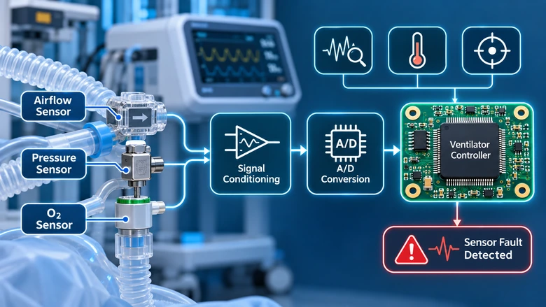
Pressure and airflow sensors provide information that the ventilator uses to monitor breathing conditions. Some designs also incorporate oxygen concentration sensors to measure the oxygen content of the delivered gas.
These sensors may produce analog or digital signals. Analog signals require proper conditioning and conversion before the controller can interpret them accurately. However, electrical noise and temperature fluctuations can interfere with this process, while sensor drift may gradually affect measurement accuracy.
Engineers should address these issues through appropriate signal filtering and temperature compensation, with regular calibration helping maintain reliable sensor performance.
The system must also recognize when sensor data becomes unreliable. Fault detection logic should identify open connections or implausible readings and trigger the appropriate response according to the ventilator’s safety requirements.
2. Reliable Motor and Valve Control
Ventilators may use electric blowers or pumps to generate airflow, while solenoid and proportional valves regulate gas delivery. The PCB controls these components through driver circuits that respond to processor commands. Accurate control is essential for maintaining the airflow and pressure required by the device.
As motors and valves operate, changes in electrical load can cause voltage disturbances and switching noise. These disturbances may affect nearby sensitive circuits, especially those responsible for processing sensor signals. Proper driver protection and power filtering help reduce such interference, while current monitoring allows the system to detect abnormal operating conditions.
Engineers must also verify that motors and valves respond correctly across the device’s specified operating range. This includes checking the reliability of electrical connections, since a loose connector or intermittent contact can interrupt actuator control even when the ventilator PCB itself is functioning correctly.
3. Stable Power Supply and Backup Power
A ventilator requires stable power for its processor, sensing circuits, actuators, and alarm system. Each section may operate at a different voltage, so the power distribution is an important part of the ventilator PCB assembly.
Voltage regulators and converters must handle changing loads without causing excessive ripple or unexpected resets. Many critical-care ventilators also use battery backup to maintain operation during external power interruptions. The power management circuitry must support controlled transitions between available power sources.
Engineers should test these transitions under low-voltage and power restoration conditions to ensure that charging circuits and power-failure alarms function as required.
4. PCB Layout, Grounding, and Electromagnetic Compatibility
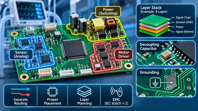
Ventilator electronics combine sensitive measurement circuits with switching power supplies and motor drivers. Poor routing can allow interference to reach sensor inputs or communication lines.
Keep sensitive analog circuitry away from high-current switching paths. Place decoupling capacitors near their associated ICs and provide suitable ground return paths.
Layer count also influences routing flexibility. A 4-layer PCB design can provide separate routing and reference layers, while more complex boards may require additional layers.
Following proper PCB component placement guidelines helps engineers organize power and sensing sections while leaving room for assembly and inspection.
The finished medical device must also meet applicable electromagnetic compatibility requirements. For example, IEC 60601-1-2 addresses electromagnetic emissions and immunity for medical electrical equipment.
5. Medical Safety Standards and Regulatory Requirements
Ventilator PCB assembly requires a documented quality approach because the electronics form part of a medical device. The applicable requirements depend on the device’s intended use and target market. Some of the relevant standards include:
| Standard | Main Purpose |
| ISO 13485:2016 | Medical device quality management systems |
| ISO 14971:2019 | Medical device risk management |
| IEC 60601-1 | Basic safety and essential performance of medical electrical equipment |
| IEC 60601-1-2 | Electromagnetic compatibility requirements |
| ISO 80601-2-12:2023 | Safety and essential performance of critical-care ventilators |
| IPC-A-610 Class 3 | High-reliability electronic assembly acceptance criteria when specified |
In the United States, the FDA’s updated Quality Management System Regulation (QMSR) took effect on February 2, 2026. It incorporates ISO 13485:2016 into the quality system requirements for applicable medical device manufacturers.
IPC Class 3 is usually considered for high-reliability medical electronics, although the required acceptance class should be defined through the product’s risk assessment and manufacturing specifications.
The ventilator manufacturer remains responsible for establishing applicable device requirements and controlling suppliers. Choosing an assembly partner with appropriate quality processes helps support that responsibility.
6. Component Sourcing and Controlled Assembly
Ventilator PCBAs often involve fine-pitch processors and precision components alongside power devices and connectors. Their reliability depends on proper component selection and consistent manufacturing processes.
Before assembly, manufacturers should verify component specifications and traceability. Any substitution affecting a critical circuit must undergo engineering review to ensure it meets the design requirements.
The PCB layout should allow sufficient space for automated placement and inspection. Properly positioned PCB fiducial marks help placement machines align fine-pitch components accurately.
When boards are populated on both sides, appropriate double-sided PCB assembly practices help minimize soldering defects. Manufacturers must also use suitable reflow profiles and control moisture-sensitive components to maintain consistent assembly quality.
7. Inspection, Quality Control, and Traceability
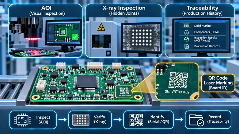
Visual inspection isn’t enough in ventilator PCB assembly to detect every manufacturing defect. Different inspection methods are needed to evaluate visible connections and hidden solder joints.
Automated optical inspection (AOI) helps detect component placement errors and visible soldering defects. PCB X-ray inspection can reveal hidden solder bridges or voids that optical methods cannot identify.
Traceability is also essential for maintaining quality throughout production. Each assembly should have records linking it to the components used and relevant inspection results. Serial numbers or machine-readable markings make this information easier to track. Techniques such as QR code PCB laser marking can help manufacturers identify individual boards and retrieve their production history when needed.
8. Functional Testing and Reliability Verification
A ventilator PCB may pass visual inspection but still have electrical faults that affect its performance. Functional testing helps verify that the circuits operate correctly under specified conditions and respond appropriately to potential failures.
The testing process should cover normal operation as well as fault conditions identified during the device’s risk assessment.
| Test Area | What Should Be Verified |
| Sensor circuits | Measurement accuracy and calibration, including fault detection |
| Motor and valve drivers | Correct actuator response and driver protection |
| Power management | Stable voltage output and reliable backup power switching |
| Alarm circuits | Proper activation under simulated fault conditions |
| Communication | Reliable data transfer through supported interfaces |
| Environmental performance | Operation within specified temperature and humidity limits |
| Electrical safety | Compliance with applicable insulation and protection requirements |
In-circuit testing (ICT) helps identify electrical shorts and open connections, while functional testing evaluates how the assembled board performs. However, PCBA testing is only one stage of verification. The completed ventilator must undergo the appropriate system-level verification to meet its safety and performance requirements.
Conclusion
Every component on a ventilator PCB assembly has a role in keeping the device operating as intended. Careful circuit design, component quality, soldering accuracy, and thorough testing help manufacturers identify potential failures early and maintain consistent production quality.
LHD TECH provides PCB fabrication and component sourcing services for ventilator electronics projects, along with precision SMT and through-hole assembly. Our manufacturing process includes AOI and X-ray inspection to help identify assembly defects and maintain consistent quality. We can handle fine-pitch components and complex multilayer boards according to your project specifications.
Contact LHD TECH today to discuss your ventilator PCB assembly requirements and request a customized quote.