Introduction to Metal Core PCBs
Printed circuit board (PCB) technology underpins virtually in every modern electronic device. As power density rises and electronic circuits shrink, to manage heat efficiently is increasingly important. Conventional PCBs—usually standard FR4 PCBs—they can trap heat, leading to reliability and performance issues. Also to address this, more PCB designers include manufacturers are turning to metal core PCBs (MCPCBs), a thermal management breakthrough.
A metal core PCB differs from traditional designs, through incorporating a metal core—commonly alu or copper—instead of, or in addition to, maybe FR4 or other non-metal substrate. This core serves as a built-in heat sink or heat spreader, dissipating heat from power-hungry or heat-sensitive components and ensuring a longer, trouble-free product life.
Fun Fact: MC PCB can transfer their heat to 8 times faster than FR4 PCBs, because the metal core’s thermal conductivity is too much higher than standard FR4.
In this article, we explore every aspect of metal core PCB technology, including its structure, types, key thermal properties, and why metal core PCBs are one of the top solutions for modern PCB design.
What Is a Metal Core PCB?
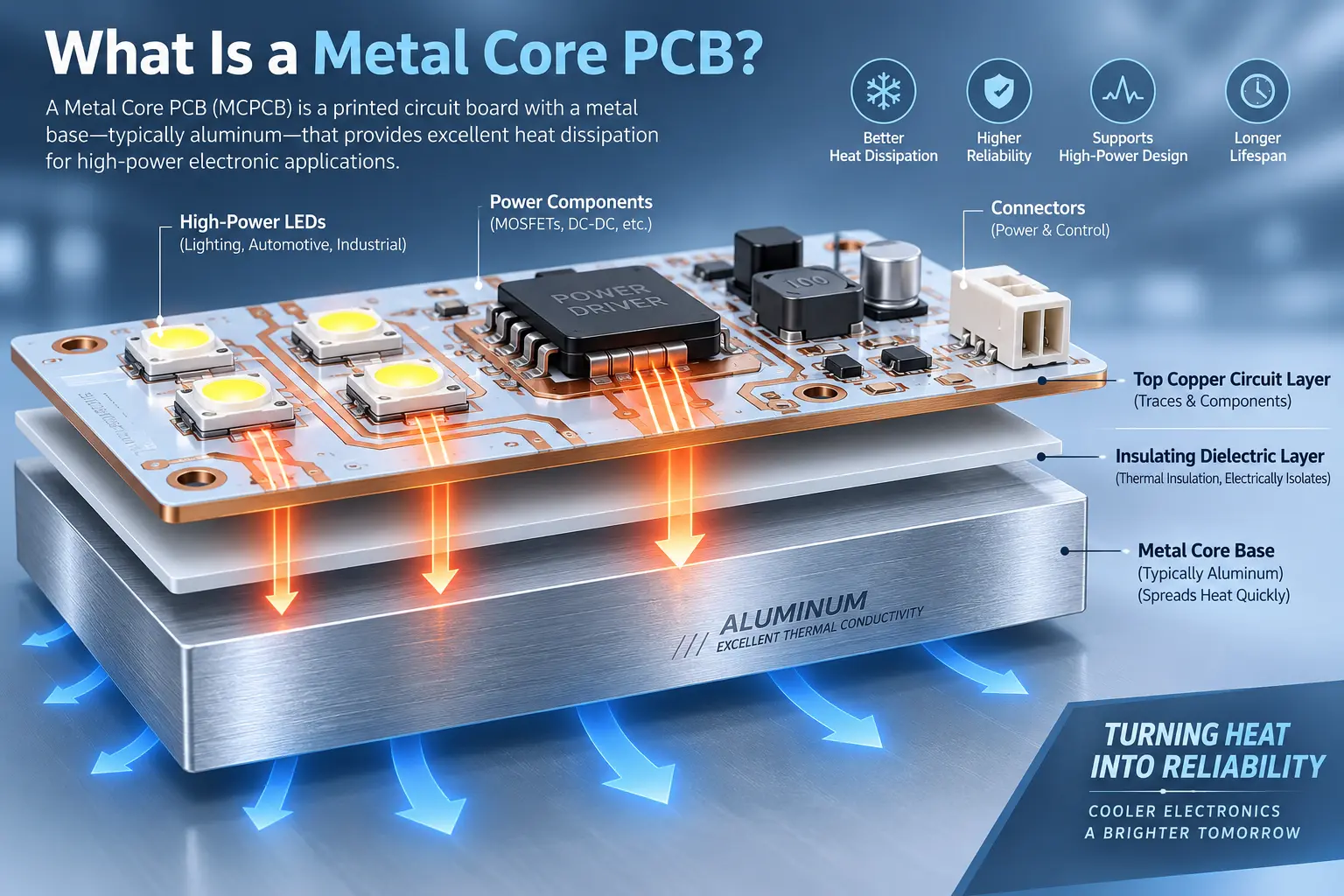
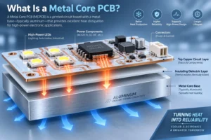
A metal core PCB (also called metal-core PCB, metal-core printed circuit board, MCPCB, or thermal PCB) is a special pcb, it also utilizes a metal core—typically alu or copper—as their central layer or substrate. This can allows for excellent thermal conductivity, then can improved structural properties, more effective heat dissipation compared to traditional FR4 PCBs.
Metal Core PCB Construction
The basic anatomy of a metal core PCB includes:
- Copper Circuit Layer: The top layer where our circuit traces are etched. Copper can range from 1oz to a standard signals to up to 10oz for high-power applications.
- Dielectric Layer: A thin, thermally conductive and electrically insulating layer,which it separates the copper layer from the metal substrate. This can ensures a electrical isolation to allowing heat transfer.
- Metal Core (Substrate): The heart of the MCPCB, either alu or copper, it serving as both thermal path and mechanical backbone. Occasionally, te iron or steel is used for specialized PCBs.
This structure was called an insulated metal substrate (IMS), and the entire assembly is known as a metal core printed circuit board.
Key Features and Terminology
- Thermal Conductivity: We can measures easily heat flows through a material. A metal core PCB typically uses a base metal that has high thermal conductivity.
- Metal Core vs. FR4: Unlike standard FR4 PCBs, MCPCBs transfer heat several times more efficiently due to their metal material as its base.
- Aluminum Core PCB: Lightweight, cost-effective, and popular in LED and power supply circuits.
- Copper Core PCB: More expensive than aluminum, boasting the best thermal performance and mechanical stability.
When Should You Choose a Metal Core PCB?
Choosing a metal core PCB makes the most sense when your printed circuit design involves high-power devices or requires advanced thermal management. Unlike standard FR4 boards, the advantages of a metal core PCB become apparent when facing:
- High Power Density: Power LEDs, DC-DC converters, motor drivers, and power transistors generate significant heat. MC PCB dissipate heat quickly from the heat source to the metal backing plate.
- Thermal Management is Mission-Critical: Applications in automotive, industrial controllers, or renewable energy,they demand reliable heat dissipation. A metal core PCB requires specific thermal analysis for safe and efficient operation.
- Design Compactness and Reliability: By using a metal core, our eliminate the need for bulky external heat sinks. Ths results in a lighter, more compact products.
- Vibration and Shock Environments: Automotive and aerospace applications, or ruggedized industrial PCBs, benefit from the mechanical durability of a metal-core PCB.
- EMI and Shielding Requirements: Copper or steel cores provide excellent electromagnetic and magnetic shielding for RF or sensitive analog circuits.
Applications of Metal Core PCBs
Metal core PCBs are essential in application,it can heat jeopardize performance, safety, or reliability. Below are normal scenarios where MCPCBs are preferred:
1. LED Lighting
- General illumination, automotive headlights, backlights in very large displays, also high-powered LED modules.
- Example: A single-layer PCB with an alu core can helps dissipate heat from high-intensity LEDs, also improving efficiency and lifespan.
- MCPCBs with white solder mask,it normally used in LED lighting for maximum light reflection.
2. Power Electronics
- Power supplies, it can switch voltage regulators, DC-DC converters, and solid-state relays.
- The metal base functions work as an effective heat spreader and removes the need to additional heat sinks.
3. Automotive and Industrial
- Motor drives, hybrid/electric vehicle control, good battery management, and rugged controllers.
- Double-sided metal core PCBsor MCPCBs with a thick copper layers help handle high currents, vibration, also thermal cycling.
4. Renewable Energy & Computing
- Solar inverters, photovoltaic modules, thenenergy storage PCBs.
- CPUs, GPUs, and power transistors in data centers often leverage MCPCBs for a efficient cooling and power management.
5. Specialized and Niche
- Audio, RF systems, and motion control circuits take advantage of copper or aluminum core PCBs for both EMI shielding and thermal properties.
Types of Metal Core PCBs & Base Materials

Metal core PCBs are classified based on the core material (base metal), circuit complexity, and applications:
Common Core Materials
Aluminum Core:
- Widely used due to its balance of cost, weight, and high thermal conductivity.
- Aluminum core PCBs are standard for LED lighting and power conversion.
- Aluminum has good heat spreading ability and is much lighter than copper.
Copper Core:
- Chosen for the best thermal conductivity and dimensional stability.
- Preferred for industrial power electronics and advanced RF circuits.
- More expensive than aluminum but ideal for applications with strict thermal requirements.
Iron or Steel Core:
- Used for specific applications requiring magnetic properties or extra rigidity.
- Provides additional EMI shielding.
MCPCB Variations
- Single-layer PCB:
- Circuit layer, dielectric layer, and metal core.
- Double-sided Metal Core:
- Copper circuit layers on both sides of the metal core, sandwiching the dielectric.
- Multilayer MCPCBs:
- Incorporates multiple copper and dielectric layers above the core for complex, high-density designs.
Metal Core Using Different Types of Metal
The types of metal used as the core material—alu then copper—each can provide different thermal conductivity and mechanical performance. Copper core PCBs have a higher thermal conductivity (it up to 400 W/m·K) than alu PCBs (up to 200 W/m·K), it will impacts the board’s ability to dissipate heat and over a efficiency.
Table: Core Materials Comparison
| Core Material | Thermal Conductivity (W/m·K) | Cost | Weight | Applications |
| Aluminum | 120–220 | Low | Light | LEDs, automotive, power PCB |
| Copper | 385–400 | High | Heavy | High-power, RF, industrial |
| Iron/Steel | 50–80 | Moderate | Heavy | EMI shielding, rugged PCBs |
Structure and Anatomy of a Metal Core PCB
Designing a metal core PCB involves understanding its unique layered architecture:
Layer Breakdown
- Copper Layer/Circuit Layer: The conductive traces for the printed circuit. The copper circuit layer maybe different from 1oz (35μm) to even 10oz in heavy-duty designs. A Proper copper foil thickness is important to handling high current and supporting effective heat transfer.
- Dielectric Layer: A thin, thermally conductive prepreg (often just 0.003–0.006-inch thick) separates and insulates the copper circuits from the metal core. This dielectric layer is engineered for high thermal conductivity, to low thermal resistance, alao reliable electrical isolation (high breakdown voltage). The dielectric is a key differentiator in mcpcb performance; choosing the right prepreg dielectric material can be the difference between a robust or unreliable board.
- Metal Core / Substrate: The heart of every metal core PCB is its metal base. This metal layer, whether it’s an aluminum or copper base metal, is what gives the board its superior heat dissipation ability. The side of the metal core in direct contact with the dielectric and copper circuits becomes a built-in heatsink (metal heatsink backing or metallic core), helping to disperse thermal loads rapidly.
Optional Layers:
- Solder mask: Often white for LED PCB uses, green or black for others.
- Silkscreen/legend: For component placement and assembly instructions.
- Resin-filled vias: For added isolation (common in multilayer MCPCBs).
Advantages of a Metal Core PCB

What makes metal core PCBs stand out compared to standard FR4 or flex PCB technology?
Top Advantages
- Superior Heat Transfer and Thermal Conductivity
- Core PCBs transfer heat 8 times faster than FR4 PCBs—a benefit that protects critical components from overheating and failure.
- Direct conductive cooling through metal core reduces risk of hot spots, ensuring even temperature distribution across the circuit.
- High Current and Power-Handling Capabilities
- Throughsupport a heavy copper layers,then a efficient heat dissipation, metal core PCBs can increase the reliability of high-power designs, like motor drivers and power converters.
- Mechanical Strength and Rigidity
- A metal layer gives the board very much great mechanical stability, its shock and vibration resistance,their dimensional stability compared to standard FR4 PCBs or even rigid-flex PCB types.
- Higher Reliability, Lower Maintenance
- Lower thermal resistance can leads to a longer operational life for LEDs, power transistors,include sensitive analog circuits.
- Fewer warranty issues due to thermal failures.
- Compactness and Cost-Effectiveness
- By eliminating the need for external heatsink components and mini PCB thickness, metal PCB can enable sleek, space-saving product designs.
Key Fact
Aluminumand copper are not only better at removing heat, but they also provide a better coefficient of thermal expansion (CTE) match, reducing stress on solder joints during rapid temperature cycling.
Metal Core PCB Manufacturing and Design
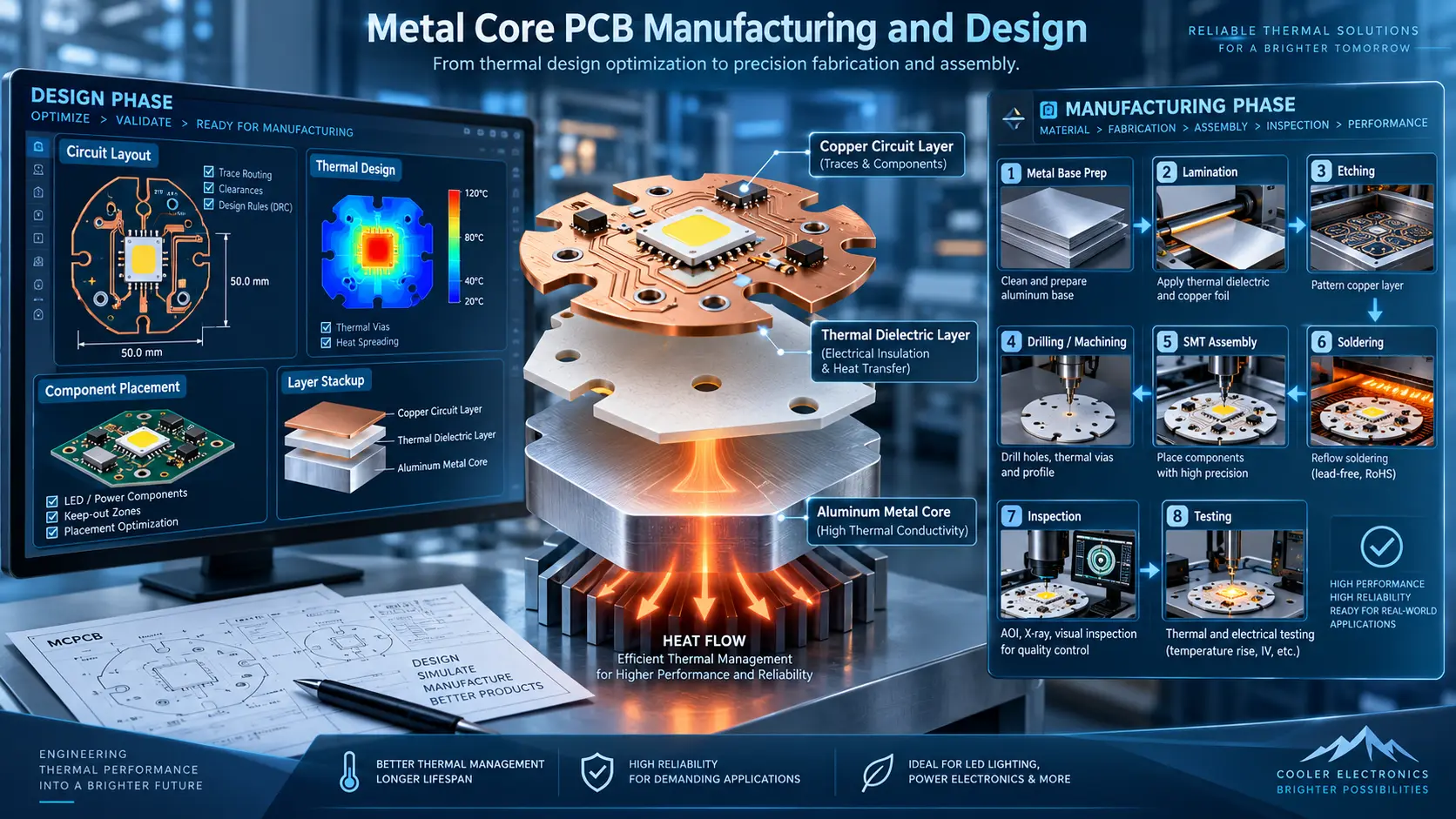
The PCB Manufacturing Process for Metal Core PCBs
- Cutting and Preparation: The metal core (often called “metal plate side”)—aluminum or copper—is cut to size, drilled, and cleaned for adhesion.
- Dielectric Lamination: A thermally conductive dielectric layer is laminated to the metal substrate.
- Copper Foil Application: Copper foil is laminated to the dielectric, forming the basis for the copper layer.
- Imaging and Etching: The copper foil is patterned using photoresist imaging, then etched to produce the desired circuit layer.
- Drilling/Routing: To lated and non-plated through holes (PTH, NPTH) are created using advanced CNC equipment capable of handling metal materials.
- Solder Mask and Silkscreen: Solder mask is applied, a silkscreen for component identification. For high reflectivity (in LED MCPCBs), white solder mask is normal.
- Surface Finish: Finishing such as ENIG, OSP, or HASL to prevent oxidation and improve solder ability.
- Final Assembly and Testing: Boards are tested for opens, shorts, breakdown voltage, in some cases, thermal cycling before shipment.
- PCB manufacturing for MCPCBs requires specialized equipment and skills, which is why choosing an MCPCB manufacturer with technical articles on PCB design and manufacturing expertise is crucial.
Tips for Metal Core PCB Design
- Always specify core material, copper weight, and dielectric characteristics.
- When designing a metal core PCB,we can place heat-generating components directly above the metal core for best heat transfer.
- For LED arrays,maximize copper pour area to spread heat more efficiently.
- Use heavy copper or thicker metal layersfor higher current or power density.
- Panelize metal PCBs carefully,as metal expands differently under heat versus standard FR4.
Metal Core PCB vs. FR4 PCB
Let’s compare MCPCBs to traditional FR4 PCBs with a focus on thermal, mechanical, and cost considerations:
| Property | Metal Core PCB | Standard FR4 PCB |
| Thermal Conductivity | 1–8 W/m·K (Al/Cu) | ~0.3 W/m·K |
| Thermal Resistance | Low | High |
| Weight | Med-high (metal core) | Low (fiberglass resin) |
| Heat Dissipation | Excellent | Poor |
| Mechanical Strength | High | Moderate |
| EMI Shielding | Good (Cu/Steel core) | Low |
| High Power Capability | Excellent | Limited |
| Cost | Moderate–high | Low (especially in large volumes) |
| Design Flexibility | Rigid (MCPCB) | Rigid, flex, rigid-flex |
MCPCB Key Takeaways
- MCPCBs are a must for engineering teams where thermal management, reliability, and power density matter more than minimal cost.
- Unlike standard FR4, metal core PCBs transfer heat more effectively, reducing the need for bulky heatsinks and enabling compact, rugged product designs.
- The main downside: Copper core PCBs are more expensive than aluminum, and both are more costly than FR4.
Heat Sinks vs. Heat Spreaders in PCB Design
Heat Sink
- External finned, metallic device (often aluminum) attached to draw heat away from the PCB or component.
Heat Spreader
- The metal core, plate, or large inner copper pour that distributes heat across the PCB. The metal core using aluminum or copper acts as a heat spreader to level out hot spots and transfer thermal energy to the enclosure or a remote sink.
MCPCBs combine these roles: their metal core or backing plate is both a heat spreader and heatsink, maximizing efficient heat transfer from the heat source to the metal backing.
Choosing and Procuring Metal Core PCBs
Checklist for Sourcing
- Specify the base metal (aluminum, copper, or iron/steel) and thickness.
- Specify the copper circuit layer weight.
- Specify the dielectric layer type, thickness, and thermal conductivity.
- Request technical data on breakdown voltage, flammability (UL 94V-0), and max current/hotspot measurements.
- Request DFM feedback—metal core PCB manufacturers often provide helpful technical articles on PCB design.
FAQs About Metal Core PCB
1. What is a metal core PCB?
A metal core PCB (MCPCB) is a printed circuit board that uses a metal base or core to improve heat dissipation. Aluminum and copper are the most commonly used metal core materials.
2. What is an aluminum core PCB?
An aluminum core PCB is a type of MCPCB that uses an aluminum substrate to transfer heat away from electronic components. It is widely used in LED lighting, power supplies, and power electronics.
3. What is the core material in a metal core PCB?
The core is typically made of alu or copper. Alu offers a good balance of thermal performance, weight, cost, but copper can provides higher thermal conductivity.
4. Which metal is commonly used in metal core PCBs?
Alu is the most commonly used metal because its good thermal conductivity, light weight structure,with competitive cost. Copper is used when higher thermal performance is required.
5. What materials are used to make a metal core PCB?
A typical metal core PCB include of a copper circuit layer, a thermally conductive dielectric layer,also a metal base or core. A solder mask and surface finishes are added during PCB fabrication.
6. What are the main types of metal core PCBs?
Common types include single-layer MC PCBs, double-layer or double-sided MC PCBs, and multi layer metal core PCBs. The structure is according to circuit density and thermal requirements.
7. How thick is 1 oz copper on a metal core PCB?
One oz of copper is approximately 35 μm (1.4 mils) thick. A Metal core PCBs can also use heavy copper,it depending on current-carrying and thermal requirements.
8. Can metal core PCBs have multiple layers?
Yes. Multilayer metal core PCBs combines from multiple copper and dielectric layers with a metal core, it base to support more complex circuits,to maintaining effective heat dissipation.
9. What are common metal core PCB problems?
Common issues include poor dielectric bonding, in sufficient thermal conductivity, delaminatio, wrong insulation thickness, drilling defects, athen thermal stress. Proper material selection and process control help prevent these problems.
10. How are metal core PCBs tested?
Metal core PCBs are typically inspected,to using electrical testing, AOI, dimensional inspection, dielectric withstand testing, and thermal performance checks,it to verify circuit integrity and insulation reliability.
Recent Trends and Future of MCPCBs
As electronics shift to a higher power density,a higher integration, the importance of MC PCBs is grows. Here are key trends and future perspectives:
- Integration of Sensors: More PCB designers can embed temperature or vibration sensors directly on metal core PCBs,then to real-time monitoring and preventative maintenance.
- Advanced Core Materials: Hybrid metal cores, mixing alu and copper, or introducing graphite and advanced ceramics,they are under heavy research to optimize both cost and performance.
- Miniaturization & Multilayer MCPCBs: Demand is growing for multilayer pcb, fine-pitch MCPCBs for advanced lighting, compact power modules, and telecom. PCB base engineering and stack-up design are evolving to support both signal integrity and high thermal conductivity.
- MCPCBs in New Markets: As electric vehicles, renewable energy, and smart infrastructure expand, MCPCBs appear in battery management, solar power, power inverte, and motion control systems.
- Sustainability: Recyclable aluminum and copper, eco-friendly dielectric material, and energy-efficient PCB manufacturing techniques are becoming industry standards, reducing the environmental impact of high-volume metal core PCB production.
Conclusion: Is a Metal Core PCB Right for You?
Metal core PCBs deliver the circuit flexibility of standard printed circuit boards alongside superior heat dissipation performance, and are widely used in modern high power systems requiring high reliability, LED lighting, automotive control units, power supplies, industrial automation equipment, solar inverters and high end computing hardware, metal core PCBs leverage their metal base material to quickly draw heat away from active components. This safeguards delicate devices and helps hardware run at full capacity.
Key Benefits:
- Superior heat dissipation via high thermal conductivity of aluminum or copper.
- Improved mechanical stability due to the metal layer.
- Lower thermal resistance keeps your devices cooler and lengthens operational life.
- Compact design with integrated thermal management—no need for bulky external heat sinks.
- Reliability and ruggedness in harsh or high-vibration environments.
Are there drawbacks? While MCPCBs come at a higher cost compared to conventional FR4 PCBs. Even so, their improved performance, mechanical robustness, reliability and space saving properties generally make the extra cost worthwhile, particularly for harsh condition applications.
If you want to future-proof your products for next-generation standards and achieve top-tier thermal performance, investing in a metal core PCB could be your best PCB design decision yet.