Introduction to VGA Connector, PCB, Pin, Pinout, VGA Connector Pinout, Cable, and VGA Interface
VGA connector,which is blue and metallic housing, it was a fixture in video display technology. On the mainstays of analog video interface technology, the VGA connector are relevant for a wide range of electronics, from legacy desktop monitors to modern industrial LCD board. As a core of its enduring utility is not just the only connector , but also the intricate relationship include the VGA connector pin out, the PCB, every individual pin, and the wir and cable choices in a display system.
Why is the VGA connector important?
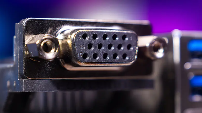
Primarily because its scope of application in video signal transmission is vast; it offers exceptional flexibility in both DIY and professional settings, while also facilitating remarkably simple integration with analog signals and certain digital adapters. Although digital cabling solutions—such as HDMI and DisplayPort—have now become ubique in the home theater and modern computer hardware markets, the VGA interface—still featuring its iconic three-row, 15-pin layout, continues to serve as a silent, steadfast workhorse behind the scenes, supporting everything from classroom projectors to industrial environments.
In this article, we will provide you with a comprehensive overview of VGA connectors—covering pin definitions, cable selection, PCB integration, pin configurations, and the various types of VGA interfaces—as well as the technical and practical details involved in VGA interface routing, repair, and troubleshooting. I am confident that this article will prove to be of immense value to engineers, electronics enthusiasts, repair technicians, and educato alike.
What is a VGA Connector? How Does It Work in Electronics and Video Signal Transmission?
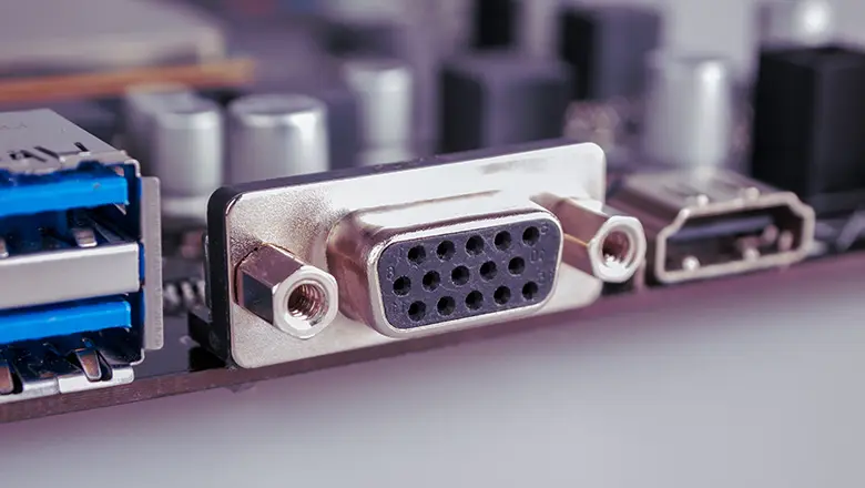
The VGA connector is a standard physical interface, the most common identifiable is a 15-pin (DE-15 or HD15) D-sub connector. The connector include both male and female, but the male connector found on cables and the female connector need to mounted on a PCB inside desktops, monitors, and projectors.
Main Functions in Electronics
- Video Signal Transmission: It ususlly carry analog RGB signals—transmitting the red, green, and blue channels for sharp color emergenc.
- Synchronizing Signals: HSync (horizontal sync) and VSync (vertical sync) signals data with a display’s cycle, in order to ensure the right update in the right time.
- Peripheral Device Interface: VGA connectors provide a universal coupling point for monitors, projectors, and also specialty devices such as oscilloscopes and industrial displays.
- Pin-Based Identification and I²C Communication: Modern implementations utilize DDC (Display Data Channel) and EDID (Extended Display Identification Data) protocols on specific pins to enable a PC to query the refresh rates and resolutions supported by the monitor.
Anatomy of the Standard VGA Connector
- 15 Pins / Three Rows: Often called a 15-pin connector, with five pins per row (hence “three rows”—sometimes incorrectly called a 14-pin connector if +5V is unused).
- D-sub Form Factor: The D-shape ensures correct, secure connection and resists improper orientation. Key pins may be blanked in order to prevent the insert errors.
- VGA Port on PCB: The port, usually is a female connector, it solder directly to the PCB, transfer the bridge between the wiring and internal signal processing circuitry.
Understanding PCB and the VGA Connector Pinout
A leading PCB (Printed Circuit Board) in the pcb industry is designed to ensure reliable, low-noise, and robust connections for the VGA port. The pinout—the mapping between each connector pin and its trace/path on the PCB—dictates the quality of video signal, resistance to interference, and long-term reliability of the device.
PCB Considerations:
- Signal Routing: High-priority pins (such as the RGB video channels,sync signals) are routed as short, straight traces to mini the signal degradation and impedance.
- Grounding: Every grounds pin on the VGA connector pin out connected to a well-designed ground or plane, important for analog video signal integrity.
- Connector Mounting: The 15-pin connector is reinforce mechanically; mechanical stress is shared across the solder joints and sometimes enhanced by additional hardware.
- Shielding: D-sub connector enclosure (the metallic component housing the pins) should be ground on the PCB for EMI shielding, especially when long cables are used or in industrial environments with lots of electrical noise.
15-Pin VGA Pinout: Detailed Diagram and Pin Configuration
The standard 15-pin VGA connector pinout (DE-15) defines exact roles for each pin:
| Pin | Signal | Description | Typical Use |
| 1 | Red Video | Analog Red signal | RGB video |
| 2 | Green Video | Analog Green signal | RGB video |
| 3 | Blue Video | Analog Blue signal | RGB video |
| 4 | ID2/Reserved | Display ID or reserved | EDID/DDC, monitor ID |
| 5 | GND | Signal ground | Common ground |
| 6 | R-GND | Red return | Signal ground |
| 7 | G-GND | Green return | Signal ground |
| 8 | B-GND | Blue return | Signal ground |
| 9 | Key/+5V | Sometimes +5V supply / key | DDC supply / blank |
| 10 | Sync GND | Ground for sync signals | VSync, HSync reference |
| 11 | ID0/Reserved | Monitor ID bit or reserved | DDC, monitor identification |
| 12 | ID1/SDATA | Monitor ID/I²C Data (DDC/EDID) | Data line for display ID |
| 13 | HSync | Horizontal Sync signal | Row timing & sync |
| 14 | VSync | Vertical Sync signal | Frame timing & sync |
| 15 | ID3/SCL | Monitor ID/I²C Clock (DDC/EDID) | Clock line for DDC/EDID |
This comprehensive pin configuration is at the heart of every VGA connector pinout reference you’ll find in the electronics world. The three rows, five pins per row setup of the 15-pin connector is a cornerstone of compatibility in countless displays, graphics adapters, and peripheral devices.
VGA Pins, Pin Configuration, and Common Wiring Practices

Getting the wiring of each pin correct is critical to successful VGA connection. Here’s what you need to know about common wiring practices for any PCB, DIY, or cable build involving the vga connector:
Wiring Tips for VGA Connector Pinout
- We canuse the correct pin configuration as per the VGA standard; mix up ground and signal pins, it can result in no image, wrong colors, or in rare cases, damage to the PCB or display electronics.
- Use individual shielded wires for red, green, and blue signals inside the cable—s is standard for professional VGA cables to reduce crosstalk and signal degradation.
- Many high-end cables wrap the entire set of 15 lines with a foil shield and then a braided shield, providing immunity from EMI.
- If fabricating your own cable, always test continuity from each pin through to the other end, double-checking against a trusted vga connector pinout diagram.
- Take care with the key pin(pin 9). Not all systems use it on +5V, and also some old devices and adapters, it will be missing or blocked. Never force a connector; it inspect for bent or missed pins.
Wiring Practices in PCB Layout
- On the PCB side, route the high-speed analog lines (pins 1, 2, 3, 13, 14) with the shortest traces can avoid right-angle turns, also can distort high-frequency analog video signals.
- Ground pins should connect with wide pours back to the main ground plane to ensure no voltage differences between grounds that might induce hum, noise, or sync instability.
- For all assemblies, the use of a female connector for the VGA port on the device’s PCB is industry standard.
Different Types of VGA: Standard, Mini VGA, and BNC Explained
The standard VGA connector—the 15-pin, D-sub (HD15)—is ery common, after we know the differences in VGA interface types,it means the difference between a working system and hours of troubleshooting.
Standard 15-Pin VGA Connector
- Foundedon PCs, projectors, displays; the universal connec for analog VGA from is the 1980s.
- Three rows of five pins, robust metallic shell, thumbscrew locking.
- Handles full spec RGB video, sync, ID, and DDC features.
Mini VGA
- Used primarily on ultra-compact laptops (older Apple iBook, Sony VAIO, etc.)
- Smaller footprint, fewer pins exposed onthe edge; sometimes it requires adapter cables to break out to a standard 15-pin.
- Often less durable—handle with care to avoid breakage.
BNC VGA
- Professional equipment (broadcast terminals, high-end CRT monitors, lab gear) sometimes escapeindividual RGB video, HSync, and VSync into five separate BNC connectors.
- Provides bettersignal integrity for long cable runs or environments with extreme EMI.
- Rare outside specialized video, lab, or industrial control contexts.
Choosing a VGA Connector: Tips for PCB Designers and Cable Users
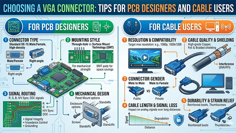
When it comes to choosing a vga connector for your latest PCB or wiring repair, consider:
- Mechanical Fit:
- Use PCB-mount connectors with long through-hole pins for extra strength.
- For portable electronics, right-angle or mini VGA may reduce board stress and save internal height.
- Electrical Quality:
- Gold-plated contacts outlast nickel, especially in humid/outdoor or high-cycle plug/unplug duty.
- Ensure shields are present and will connect to PCB ground reliably.
- Type and Adapter Readiness:
- If connecting to a modern TV/monitor, consider boards with HDMI, DisplayPort, and VGA all available—ensure your pinout supports adapters like VGA to HDMI, VGA to DVI, etc.
- Bulkhead Mounting:
- For kiosks or wall plates, use retaining nuts or flanges for additional cable strain relief, so torque isn’t applied to PCB solder joints.
VGA Cable Selection: Impact on Signal Degradation and Video Transmission
Select the right VGA cable is a basing aspect of maintaining video quality in the analog vga system:
Factors Affecting Signal Degradation
- Cable Length: Signal quality have longer runs (>5m). At 10-30m, severe signal attenuation causes ghosting, blurred text, and also the desaturated colors.
- Shielding: Double-shielded (foil and braid) cables must in environments with lots of RF noise or fluorescent lighting.
- Gauge of Wire: Lower resistance, thicker wires mean less signal loss—essential for high-resolution (SXGA or UXGA) applications over any distance.
VGA Adapter Solutions: VGA to DVI, RCA, and Digital Cable Conversions
Adapters allow legacy VGA interfaces to connect to new displays or video systems—even when digital cable is required downstream.
Types of VGA Adapters
- VGA to DVI Adapter:
- Connects analog VGA to a monitor’s DVI-A port.
- Only works if the monitor’s DVI supports analog signals (many support only digital DVI-D).
- Useful for graphics adapters that only output VGA.
- VGA to HDMI Adapter:
- Requires active electronics; converts analog VGA and separate audio to HDMI’s digital stream.
- Many such adapters are external “dongles” with USB or wall power.
- VGA to RCA (Composite):
- Used to connect a computer (via analog video adapter) to older TVs.
- Expects only standard definition (SD) video—massive quality loss, not suitable for reading fine on-screen text.
Tips on Adapter Use
- Use only high-quality, well-shielded adapters. Poor adapters often introduce flicker, sync instability, or outright no signal, especially with long cables.
- Each additional adapter or conversion step increases risk of signal degradation. Direct VGA-to-display is always best for analog video signals.
- Carefully check the supported resolutions and refresh rates; mismatches may result in “unsupported mode” messages.
VGA Connector to Connect Monitors, TVs, and Peripheral Devices
The standard VGA connector is a workhorse for connecting electronics:
- PCs to Monitors: The classic use—any desktop with a VGA port can display video on CRT, LCD, or even modern flat panels (if they support VGA).
- Laptops to Projectors/TVs: Mobile PCs often included a VGA port for quick projection; with the right cable and pinout, almost any display is compatible.
- Kiosks, Arcade Machines: VGA’s robust, thumb-screw-secured male-to-female connector is prized in high-vibration or public use settings.
- Peripheral Device Integration: Oscilloscopes, embedded development boards, digital signage—VGA remains common for quick integration where plug-and-play is needed.
Tip for Installations: Always test a complete VGA connection before equipment is finalized in racks or kiosks, especially if using extensions or multiple adapters. Flaky connections can lead to hours of wasted troubleshooting.
Common Misconceptions About VGA and Misunderstandings About Wiring and Pinout
Despite the longstanding popularity of the VGA interface and the ubiquity of the VGA connector, many users and even electronics professionals hold common misconceptions about the correct wiring, pinout, and capabilities of VGA systems.
Debunking Top Misconceptions About VGA Connectors and Cables
VGA cables can transmit audio
This is FALSE. Standard VGA connectors and cables carry only analog video signals—specifically, RGB video signals and sync lines. Audio transmission is not supported, so connecting speakers or expecting sound through a VGA cable is a common and frustrating mistake.
All 15 pins are always connected and used
Not quite! While the standard 15-pin connector has fifteen pins arranged in three rows, not all devices use every pin. For example, pin 9 (key pin) is often unconnected, especially on older hardware or VGA connectors that predate the DDC/EDID standards. Some low-cost cables may skip certain IDs or ground pins, which can cause compatibility problems.
VGA is just for computers—no TVs or other devices
Incorrect! While VGA started with computers and monitors, it’s used in many peripheral devices: from projectors to arcade game boards, oscilloscopes, medical equipment, and even modern TVs and graphics adapters until the digital transition became dominant.
If a VGA cable fits physically, it will always work electrically
There are subtle but crucial differences among standard, mini VGA, and BNC/RGB configurations. Forcing a cable into a port—even if the d-sub connector fits—can misalign the actual signals if the pin configuration or adapter is wrong, risking signal loss or, rarely, device damage.
VGA supports infinite-length cables
No VGA cable is immune to signal degradation. Even the best shielded analog VGA cables show visible ghosting, color bleeding, and sync jitter above 10-15 meters unless boosters or repeaters are used.
VGA cables are all the same quality
Far from reality—cable can interfere due to poor manufacturing, inadequate shielding, or thin conductors, introducing analog noise. Always use reputable brands and avoid no-name “freebie” cables that come with old monitors.
Advanced PCB Tips: Avoiding Signal Degradation for RGB Video and Sync
Getting strong, clear video from your analog VGA interface isn’t just about picking the right connector or cable. PCB design plays a key role in reducing interference and delivering consistent, clean video signals.
Critical PCB Design Principles for VGA
- Prioritize Analog Routing: The paths of each VGA pin ( pins 1, 2, 3 for RGB, and 13, 14 for sync) should be shorter and directer. The longer the trace, the greater the risk for signal loss, reflections, and interference from digital logic switching close.
- Maintain Consistent Impedance: Trace width and spacing are not arbitrary! For high-resolution video (>800×600), match the impedance (typically 75Ω) of PCB traces,it expected by the VGA standard, to reduce ringing and ghosting.
- Optimize Ground Connections: Each ground pin (5, 6, 7, 8, 10) should connect to a broad, solid ground pour. In order to avoid daisy-chaining or “star” grounding, introduces potential voltage offsets on high frequency.
- Use High-quality Soldering Methods: Proper pad plating (ENIG rather than HASL) and enough solder flow at the connector pins extend the working life of d-sub connector.
- Shielding and Filtering: When your PCB want housed in high-EMI environments, we can use metal backshells/shields tied directly to PCB ground and consider LC filters or the sync lines.
- Thermal Management: Hot environments can cause thermal drift and dry out the solder on connector interface. If your design support, we will use mounting brackets to divert mechanical and thermal load away of pads.
VGA Pinout Troubleshooting and Repair: Techniques for Cables, Adapters, and PCBs
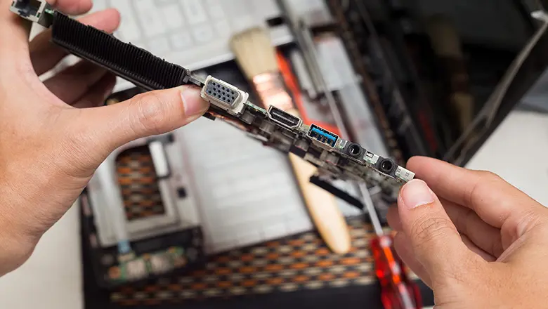
Be able to troubleshoot a VGA connection—no matterr on a cable, adapter, or the embedded PCB—it is an basic skill in the electronics world.
Step-by-Step Guide for Troubleshooting VGA Connectors and Pinouts
- Visual Inspection: The bent, missing, or corroded pins on the 15-pin connector. Ensureare recessed, missing, or shorted by stray solder if inspecting a PCB’s solder side.
- Pinout Check with a Multimeter: Set your multimeter to continuity mode. Check each pin from end to end—especially RGB, sync (13/14), and grounds—against a trusted vga connector pinout chart. Be wary of “floating” grounds or shorted pins.
- Swap and Isolate: Try another cable, adapter, monitor, or source one at a time. If you swap three cables and all fail, the issue is likely on the PCB itself.
- Test Patterns: Use a VGA video pattern o generateor your PC’s color test images. missing, out-of-alignment colors indicate a broken and miswir RGB line.
- Move/Reseat Connectors During Testing: If image quality momentarily improves when you touch or move the cable or connector, there isa cold solder joint, broken ground, or intermittent break in the cable.
Common Repair Actions
- Reflow Solder Pads: If tjere problems with the male connector or female connector on the PCB, often arise to mechanical stress; touch up and reinforce with fresh solder.
- Replace Damaged Connectors: If several of the 15th pins are bent or snapped, we can replace the entire d-sub connector.
- Upgrade Cable or Shielding: In challenging environments, swap in a thicker, double-shielded cable to reduce some
- Use Shorter Wires for Internal Builds: For in-enclosure wiring, the shorter and straighter, the better.
Case Study: Designing a Leading PCB for a VGA Interface in Industrial Applications
Let’s examine how a leading PCB in the pcb industry solved recurrent issues with VGA interface reliability in a factory automation system.
Background: A manufacturer of industrial control panels notice that if we increase downtime in production lines. Inspection revealed the culprit: low-cost VGA cables and poorly secured PCBs led to signal loss, random color shifts, and no display on floor monito.
Steps Taken:
- Connector Selection: Switched from generic connectors to gold-plated, reinforced 15-pin d-sub connectors with flanged mounting for secure chassis attachment.
- Improved PCB Layout: All VGA video signal traces were routed from the connector to the output with uniform width and minimal bends, some full ground plane was placed beneath all high-frequency lines.
- Upgraded Shielding and Cabling: Cables can switch to double-shielded, factory-certified VGA cable, terminated with high-strength strain relief to vibration and cable movement.
- Adapter Readiness: Recognizing the clients were transitioning to digital monitors, the redesigned PCB and port pin out supported plug-and-play VGA-to-DVI and VGA-to-HDMI adapters, with the clear wiring legends for field workers.
Conclusion: The Role of the VGA Connector, Pinout, and PCB in Today’s Electronics
Although digital interfaces have become widely used today, the VGA connector – with its defined pin layout, strict PCB routing requirements, and reliable cabling design – still plays an essential role in global video and display systems. Whether for consumer electronics, public information terminals, or industrial control applications, a solid grasp of VGA pin definitions, configurations, and cable selection will ensure stable performance, less downtime, and strong compatibility between legacy and modern equipment.
Whether you’re doing basic wiring, installing a graphics card, or designing high-performance PCBs for new products, never overlook the importance of every single connection. Every pin, every solder joint, every shield, and every ground can directly impact the stability and performance of your entire system.
Frequently Asked Questions Regarding VGA, PCB, Pin, and Cable
Q: What is the correct pinout for a standard VGA connector?
A: See the 15-pin VGA connector pinout chart in this article; always follow the official DE-15 configuration for both PCB and cable builds.
Q: Can a cable interfere with signal quality if it’s too long or low quality?
A: Yes! Signal degradation is the number one affect of blurry or unstable images. In order to choose thick, double-shielded cables to avoid exceeding 5-10 meters in standard environments.
Q: Is it possible to use a VGA to RCA or VGA to HDMI adapter for any device?
A: VGA to RCA (composite video) adapters only work for low-resolution analog video transmission, it requires the right graphics adapter support or a dedicated signal converter. A VGA-to-HDMI adapter must be an active convertr with built-in processing circuitry to change analog VGA signals into digital HDMI signals. A simple passive cable cannot do this conversion. Pls to ensure your device can supports the correct signal format before using one adapter.
Q: What is the difference between a male connector and a female connector in VGA wiring?
A: VGA cables and devices together with male pin connectors, when VGA ports on monitors, PCB, a graphics cards are female socket types. In order too make a secure and proper connection, we always check the male and female connectors whether fully&correctly matched.
Q: Why does the standard 15-pin VGA connector have three rows of five pins each?
A: This configuration, also known as the D-sub (DB-15 or HD15) connector, provides separation for each RGB color signal, the ground returns, and data/ID signals. This design achiev precise, independent routing while simultaneously ensuring the signal integrity of analog video signals underVGA standard..
Q: My device has only 14 pins visible in the VGA port—what gives?
A: Sometimes, pin 9 (key pin) is missing or blocked for anti-insertion protection or because +5V is not needed. This is safe and normal as long as other pins are present and wired correctly per the VGA connector pinout.
Q: Do all VGA cables provide the same video resolution support?
A: No. Your existing cable’s quality, shielding, and internal wiring gauge decide the analog video signals transfer. In high-resolution (e.g., UXGA, 1600×1200), we can choose a cable for that bandwidth and avoid consumer-grade cables—even the short production.
Q: Can improper PCB wiring or a faulty cable cause device failure?
A: Yes. Miswiring the VGA pinout or using a damaged cable can not on;y short critical pins, cause signal cross-talk, but also stress the electronics of your graphics adapter, monitor, or embedded device. Pls remember to double-check your PCB layout, adapter, wire.
Q: Is a digital cable (HDMI/DisplayPort) always better than analog VGA?
A: Not in every time. The digital cable standards like HDMI and DP offer higher resolutions, audio transfer, and better immunity to interference, some legacy systems and environments with high EMI or long cable runs rely on the robustness of analog VGA. Use a VGA connector is usually very reliability and compatibility.
Q: When should I use a mini VGA connector instead of a standard 15-pin VGA?
A: Use a mini VGA connector, the space is a previous. Remember: a mini VGA adapter is will be require to break out to the standard, 15-pin configuration for monitors and projectors.
Q: Can I use the same VGA cable for both PC and video game consoles?
A: If both devices use a standard VGA output, if you match the connector pinout precisely, then yes. Some RGB video or arcade boards, however, might require custom cabling—always consult your console’s or PCB’s pin configuration documentation.