
Multimeter Symbols: A Guide to All Dial Icons
Introduction: Why Every Multimeter User Need a Guide to Multimeter Symbols
Whether you’re a homeowner, electrician, DIY enthusiast, or student, understand multimeter symbols is essential for safely and effectively diagnose electrical problem. Multimeter—tools for measure voltage, current, and resistance—feature a dizzy array of symbol print around their dial and on their digital display. At first glance, these can seem cryptic. But with a clear guiding to multimeter symbol, you’ll know exactly which test function to select, what those symbol mean, and how to use your multimeter for accurate, safe measure.
Understanding what multimeter symbols mean—such as voltage symbol, resistance symbol, or the symbol resemble a Wi-Fi icon for continuity—prevent mistake, protect your device, and ensure every measurement is both accurate and safe.
Multimeters: The Essential Tools for Measuring Electricity Safely and Effectively
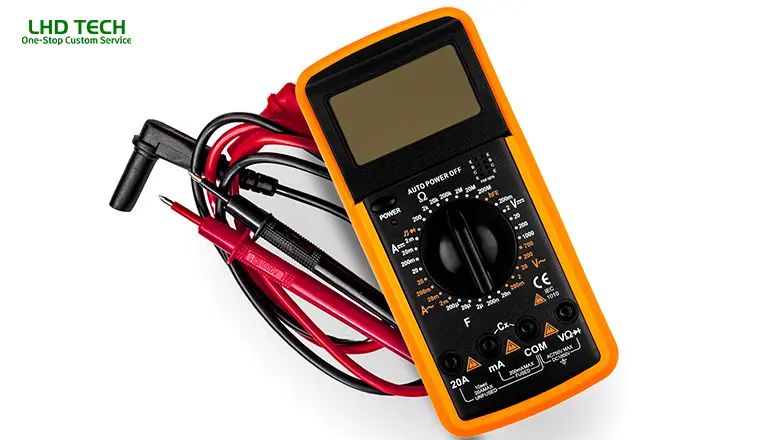
Multimeter—sometime call VOMs (Volt-Ohm-Milliammeters)—were invent by Engineer Donald Macadie in 1920. His goal was to combine several tools for measure electric current, voltage, and resistance into a single, portable device. Modern digital multimeter take this idea even further by offer feature like diode test modes, millivolts (mV), microamps (µA), temperature setting, hold function, and auto range option.
Why Every Multimeter Belongs in Your Toolkit:
- Measures both dc and ac voltage and current.
- Checks resistance by sending a safe current through a component or wire.
- Identifies circuit problems with continuity and diode test function.
- Measures temperature, frequency, and capacitance (advanced models).
- A multimeter, with its two leads and clear test function symbols, is one of the most essential tools for anyone working with electricity.
Guide to Multimeter Symbols—What These Symbols Mean

This section is your practical, visual guide. Let’s explore what the multimeter symbols mean—from voltage, current, resistance, and continuity to special functions.
Voltage Symbols
Voltage is represented by a capital V, often accompanied by additional marks:
- V~ (Alternating Current): AC voltage, symbolize by a capital V follow by a wavy horizontal line (“~”). Use for wall outlet, AC motor, or appliances.
- V⎓ (Direct Current): DC voltage, marked by a capital V and a line with a dashed line or dots underneath. This horizontal line represents steady, unidirectional voltage—used for batteries, a DC power supply, or electronics.
- mV (Millivolts): “mV” stands for millivolt, use to measure very small voltage, such as sensor output on microcontroller.
Current Symbols
Current, the flow of electric current, uses a capital A:
- A~: AC current measurement. Ideal for alternating current circuits in your home.
- A⎓: DC current measurement—solid and dashed horizontal line above the A, for testing battery or low-voltage electronics.
- mA (Milliamps), µA (Microamps): These smaller denominations are critical for measuring current in sensitive circuits or sensors.
Resistance and Continuity Symbols
Resistance is denoted by the Greek capital omega: Ω.
- Ω (Ohms):Used for measuring resistance in wires, resistors, or appliance parts.
- kΩ (kilo-ohms), MΩ (mega-ohms): Larger resistance values.
- Continuity (Wi-Fi-like or right-facing sound bars): This symbol resembles a series of arcs or Wi-Fi signal bars. It means your multimeter will beep when the circuit is complete (closed).
Additional Symbols You’ll Find
- Diode Test Function (→|–): A right-facing arrow and vertical line, used to test diodes and check for AC to DC conversion.
- Capacitance Test ((|—): Measures the value of capacitors in farads.
- Temperature Setting (thermometer): Measures ambient air or surface temperature with a thermocouple.
- Hz (Hertz): Frequency, found when measuring AC signals.
- Hold (button freezes reading): Usually marked with “HOLD”, holds the current reading.
- Shift/Function Button: For secondary dial functions (often in yellow or blue).
Voltage Symbols: How Multimeters Measure Both DC and AC Voltage
A core use of multimeters is to measure both DC and AC voltage. Knowing the correct voltage symbols and how to use them is key to getting the right results.
AC or DC—Choosing the Correct Symbol
- Alternating Current (V~): Plug the leads into the COM and VΩ jacks. Place the red lead on the hot side and the black on the neutral/ground. Select the V~ symbol on the dial.
- Direct Current (V⎓): Used for batteries, DC adapters, power supplies, and solar panels. Always ensure the correct symbol resembling a V with solid/dash lines is selected before testing.
Millivolts (mV): Some digital multimeters offer a mV mode for testing small DC signals like analog sensors or signal amplifiers. This precision function is often accessed via the shift button or a secondary dial position.
Current Measurements: AC or DC, Milliamps, and Microamps
Electric Current—How Symbols Guide You
To measure electric current, every multimeter uses symbols to differentiate between:
- DC Current (A⎓): For measuring current from a battery, solar device, or DC power supply.
- AC Current (A~): Used in home circuits or larger appliances.
- Milliamps (mA) or Microamps (µA): For precise readings in electronics, LED circuits, or sensors. Some multimeters can measure down to microamps, vital for testing standby power draw or instrument signals.
Tip: Always insert the red lead in the appropriate jack (often mA, µA, or 10A) when measuring current, as too much current through the wrong jack can blow the fuse.
When to Use Each Current Setting
- Use A~for checking household appliance draw.
- Use A⎓or mA/µA for circuits powered by batteries or small DC sources (RC vehicles, Arduino projects, etc.).
Resistance Symbols and the Continuity Test Function
Resistance Symbols Mean
Understanding what resistance symbols mean helps you troubleshoot open or short circuits, bad connections, and component faults.
- Ω: Basic resistance check—used to measure resistors, wire integrity, switches, or appliance elements.
- kΩ / MΩ: Measuring higher resistance values, crucial for insulation tests, certain sensors, or electronic components like thermistors and photoresistors.
- Continuity test function: Identified by a symbol resembling sound bars or a small “Wi-Fi” icon. This test function quickly checks for an unbroken path (closed circuit). When using the continuity setting on your multimeter dial, a beep signals continuity; silence indicates an open circuit.
- How multimeters can also measure resistance: In resistance mode, the multimeter will display the value of resistance by sending a tiny electric current through the component and measuring voltage drop. This is called the “ohmmeter” function.
Digital Multimeters: Decoding Functions Like the Diode Test Function and Measuring Temperature
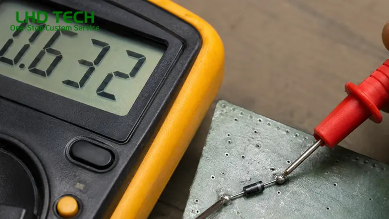
Digital multimeters have revolutionized electrical testing, providing clear displays, greater precision, and a host of advanced features beyond older analog models.
Diode Test Function
- Found on most digital multimeters, this function is represented by a right-facing arrow meeting a vertical line (→|–).
- The diode test function is used to check components like diodes and LEDs, which only conduct electricity in one direction (from anode to cathode).
- How it works: Place the red lead on the anode and black lead on the cathode; your multimeter will display a voltage “drop” (typically 0.5V–0.7V for standard silicon diodes). A “0” or “OL” means a short or an open diode, respectively.
Measuring Temperature with Digital Multimeters
- The temperature set (thermometer symbol) allow you to use a thermocouple to check wire, transformer, or even ambient air temperature.
- Insert the thermocouple into the correct jack (often sharing the VΩ port or a dedicated socket) and select the temperature option on the dial.
- Digital multimeter can measure both Celsius (°C) and Fahrenheit (°F). Always check the display for the scale shown.
- Example Use: Diagnosing overheating component in a DC power supply. If a transformer run hot to the touch, compare its temperature against manufacturer spec to identify issues early.
Other Useful Digital Multimeter Features
- Hold button: Pressing this button freezes the reading so you can safely record the measurement.
- Auto range: Enables the meter to automatically select the proper range for voltage, current, or resistance—great for measuring unknown quantities quickly.
Auto-Range Multimeters vs. Manual Range Multimeters
One of the best features in modern digital multimeters is the option for auto-range. Understanding the difference between auto range and manual range helps you use every multimeter more efficiently.
Auto-Range Multimeters
- Automatically find the optimal scale for whatever you’re measuring (voltage, current, resistance, etc.).
- This makes your measurements both faster and safer, as there’s less risk of accidentally overloading the display with “OL” errors.
- In auto-range mode, simply select the measurement type (like V⎓ for DC voltage) and let the tool do the rest.
- Safety tip: Auto-range multimeters are ideal for beginners, since selecting the wrong range is a common cause of user error in manual models.
Manual Range Multimeters
- Require you to set the range on the dial manually (e.g., 2V/20V/200V for voltage).
- Provides more direct control and can offer slightly finer resolution for advanced users—especially useful for troubleshooting sensitive electronics.
- Always start with the highest range and work down until you get the most accurate reading.
Quick Comparison Table:
| Feature | Auto-Range Multimeter | Manual Range Multimeter |
| Speed | Faster | Slower |
| Safety/Ease | Beginner-friendly | Requires user knowledge |
| Accuracy (for pros) | Good, but may overshoot | Fine-tuned control |
Understanding the Test Function Dial, Function Buttons, and Three Jacks
Test Function Dial
The dial at the center of every multimeter is your “steering wheel” for all measurements. Printed around the dial are all primary and alternate symbols you’ll encounter.
- Turn the dial to select voltage, resistance, current, or test functions like diode, continuity, capacitance, or temperature.
- Some advanced models require the use of a shift button or function button (often labeled “Fn”) to access secondary test function modes that share a dial position.
Three Jacks and Lead Placement
- COM Jack: Always plug the black lead here for every test.
- VΩ or mAVΩ Jack: Insert red lead when measuring voltage (V), resistance (Ω), continuity, diode test, or small currents (milliamps, microamps).
- 10A or A Jack: For high-current measurements. Only use this jack for temporary tests at high currents to avoid damaging your meter’s internal fuse.
Place the red lead into the appropriate jack for your measurement—failure to do so can damage your meter.
Reading the Display: What Your Multimeter Will Display and How to Interpret It
Digital multimeters will display
- The numeric result plus the symbol or unit you’re measuring (V, A, Ω, °C, etc.).
- If set to manual range, expect to see “OL” if the value exceeds your range—switch to a higher setting.
- In continuity mode, your multimeter will beep and/or show “0” if the circuit is closed.
- In diode test mode, the meter displays forward voltage drop (typically 0.5V to 0.7V for a silicon diode).
- When auto-range is active, the meter cycles its internal scales to present the easiest-to-read value.
- Tip: Always note decimal points—1.00 V, 10.0 V, or 100 V are very different! Auto-range makes this easier, but always confirm on the display.
Pro Tips for Using Multimeter Symbols Safely and Effectively

- Always start with the highest range when unsure of what to expect in any circuit.
- Remove at least one probe from the circuit before switching test functions on the dial to avoid meter damage.
- Never measure voltage in current mode, or vice versa—this is a frequent cause of blown fuses and may harm your meter.
- For sensitive measurements (e.g., microamps), ensure your leads and jacks are clean and check for “zero error” by shorting leads before use.
- Always remove the batteries from the device under test when checking resistance or continuity.
- Replace multimeter fuses only with manufacturer-specified ratings for safe, effective operation.
- Measure temperature only with compatible probes and in environments within meter specs.
- The hold button is invaluable: in tight space or awkward position, take the measurement then button freezes the value for review.
Conclusion: Mastering Multimeter Symbols for Safe and Effective Measurement
Understanding and use multimeter symbol is not just about reading little icons on a dial—it’s about unlocking the full power, versatility, and safety of one of the most essential tools for measuring all aspects of electricity. With this guide to multimeter symbols, you can approach household, automotive, or electronic troubleshoot with clarity and confidence:
- Always use the correct symbol for the function you need—ac or dc voltage, resistance, or electric current.
- Remember how to plug the leads, select the appropriate jack, and interpret what your multimeter will display.
- Recognize the importance of range mode: auto-range multimeters are great for new users, while manual range multimeters give pros absolute control.
- Use advanced features like the diode test function, hold button, and shift button to safely and effectively unlock additional test capabilities.
Frequently Asked Questions About the Multimeter Direct Current Symbol
Q: Why do some multimeters only show “DCV” or “DCA” without a symbol?
A: Many older or budget meters use abbreviations due to space or cost. “DCV” means direct current voltage. Always double-check the user manual if anything is unclear.
Q: Can I use the DC voltage mode (V⎓) to check the output of a laptop charger?
A: Yes, if the charger/manual specifies a DC output (such as 19V). For AC output chargers, always use V~.
Q: What’s a safe way to measure car battery parasitic drain with the DC current symbol?
A: Set the dial to A⎓, use the 10A port, and connect the meter in series with the negative battery cable and battery post. Most healthy vehicles with all systems off draw under 50mA. Anything higher may indicate an electrical leak or aftermarket accessory issue.
Q: Why is there “OL” on my meter?
A: OL means overload—measurements exceed what the selected range allows, or in resistance/continuity mode, it means an open circuit.
Q: My meter doesn’t beep during continuity testing, but shows low resistance. Why?
A: Some meters only beep below a certain resistance (commonly 40Ω–150Ω), above which the continuity buzzer stays silent. Check your manual for specifics.