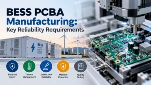

Battery energy storage systems (BESS) are expected to work for a long time. They can sit in a cabinet or container for years and cycle through charge and discharge every day.
These systems depend on electronics that can withstand continuous operation. Much of that responsibility falls on printed circuit board assemblies (PCBAs). These boards monitor battery conditions and control electrical equipment. They also help the system respond when something goes wrong.
So, imagine a faulty connection or poorly insulated circuit. Won’t it affect the reliability of an entire battery installation? It can cause lost capacity or a thermal event.
This makes reliability in BESS PCBA manufacturing deserve its own checklist. Let’s look at the key requirements that ensure these circuit boards operate safely and maintain consistent performance throughout their intended service life.
What Is a BESS PCBA, and Why Does Reliability Matter?
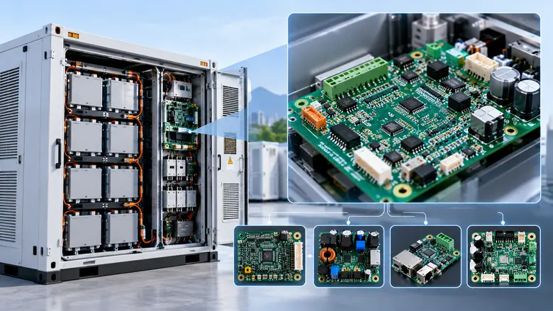
A BESS PCBA is an assembled circuit board that supports the monitoring, control, protection, or power management functions of a battery energy storage system.
Different boards handle different responsibilities. Some monitor individual battery cells, while others manage communication between components or control electrical switching.
Common BESS PCBAs include:
- Battery Management System (BMS) boards: Monitor cell voltage/temperature and other battery conditions, along with supporting protection and balancing functions.
- Power control boards: Control switching devices and other electrical functions.
- Communication boards: Exchange operating data between battery racks, controllers, and energy management systems.
- Monitoring and auxiliary control boards: Support temperature monitoring, cooling equipment, sensors, and other system operations.
These boards may be exposed to electrical noise, temperature changes, moisture, and long operating periods. Plus, manufacturing defects can also be difficult to detect once the system has been installed. For example, an intermittent solder connection might appear harmless during initial testing but eventually interrupt communication or monitoring.
Failure modes in a BMS are unforgiving. For this reason, manufacturers must consider long-term performance a crucial reliability measure during the entire PCB assembly manufacturing process.
1. Electrical Insulation and High-Voltage Safety
Commercial BESS installations can operate at hundreds of volts, with some systems reaching 1,500 V DC. PCB layouts must account for working voltage and environmental conditions.
Two important design requirements in BESS PCBA manufacturing are:
- Creepage: The shortest distance between conductors along an insulating surface.
- Clearance: The shortest distance between conductors through air.
The required distances depend on voltage, pollution degree, material properties, and insulation requirements. IEC 60664-1 provides relevant guidance for equipment within its scope.
Manufacturing reviews should check isolation barriers, PCB slots, connector placement, and critical spacing. Also, note that ordinary PCB solder masks should not be treated as a certified high-voltage insulation barrier.
2. Accurate Battery Monitoring and Protection
BMS boards read cell voltages and temperatures so controllers can catch unsafe conditions. Small measurement errors can skew balancing and protection decisions. Therefore, component placement, sensing connections, and calibration all deserve careful verification.
Functional testing should cover:
- Voltage and temperature measurement accuracy
- Overvoltage and undervoltage detection
- Sensor faults and communication failures
- The protection responses the system expects
- Interfaces such as CAN or RS-485, where they’re used
Manufacturers can feed controlled fault signals into the board and confirm it reacts correctly. Complete protection also depends on firmware and external switching hardware, so board-level results are one piece of the picture.
3. Heat Management and High-Current Paths
Heat can shorten component life and damage solder connections. MOSFETs, current-sensing shunts, regulators, and power connectors are common areas of concern. A board that runs fine on an open bench can get much hotter inside an enclosure with limited airflow.
Good thermal design includes:
- Suitable copper thickness and trace widths.
- Thermal vias and copper areas for heat spreading.
- Adequate spacing around heat-generating components.
- Effective thermal paths to cooling structures
Heavy-copper PCBs can support higher current, but they also affect manufacturing. Thick copper absorbs more heat during soldering, so reflow profiles must be adjusted to achieve reliable joints. Thermal imaging and load testing can help identify hotspots before production begins.
4. Solder Joint Durability
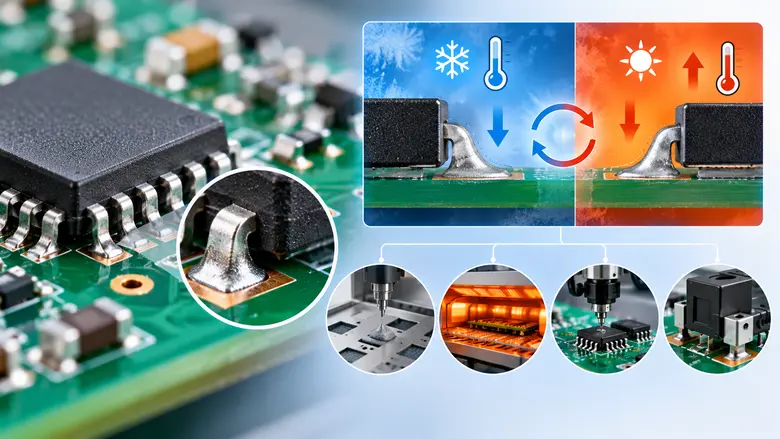
Temperature changes cause PCB materials and components to expand at different rates. Repeated cycling places mechanical stress on solder joints, which causes fatigue cracks over time.
Large components and heavy power devices may be vulnerable depending on their mounting and operating conditions.
Manufacturers can reduce these risks during BESS PCBA manufacturing through:
- Correct solder paste volume and pad design.
- Validated reflow temperature profiles.
- Accurate component placement.
- Suitable mechanical support for heavy parts.
5. Safety Standards and Compliance Requirements
BESS manufacturers also need to understand the standards that apply to their products and target markets. Different standards address different parts of the system:
| Standard | Relevance to BESS Manufacturing |
| IPC-A-610 | Acceptance criteria for assembled PCBAs |
| IPC J-STD-001 | Soldering process and workmanship requirements |
| IPC-6012 | Qualification and performance requirements for rigid PCBs |
| IEC 60664-1 | Insulation coordination for equipment within its defined scope |
| IEC 62619 | Safety requirements for industrial lithium cells and batteries, including stationary applications |
| UL 1973 | Safety evaluation of batteries used in stationary and certain other applications |
| UL 9540 | Safety evaluation of complete energy storage systems and equipment |
| UL 9540A | Test method for evaluating thermal runaway fire propagation |
For international projects, IEC 62619:2022 is particularly relevant to lithium batteries used in industrial and stationary energy storage applications.
In North America, UL 1973 and UL 9540 are important parts of the battery and energy storage system safety framework.
UL 9540A serves a different purpose. It provides a testing methodology for assessing thermal runaway propagation and associated fire hazards.
The exact standards and certification obligations depend on the system design and applicable regulations.
6. Moisture, Contamination, and Protective Coatings
BESS enclosures may experience humidity and temperature changes that encourage condensation. Moisture and contamination can contribute to corrosion, along with leakage currents and intermittent electrical faults.
Flux residues and other contaminants should be controlled through validated cleaning and handling procedures. Our circuit board cleaning guide explains common cleaning methods.
Additional protection may include:
- Conformal coating: A thin protective layer applied to selected PCB surfaces.
- PCB Potting: A protective compound surrounding components or the assembly.
Silicone coatings can be useful where flexibility and temperature cycling are crucial. However, coating chemistry, thickness, cleanliness, and component compatibility all need evaluation. A poorly chosen coating can add mechanical stress or trap contamination against the board.
7. Connector and Mechanical Reliability
Connectors are another area that needs attention in BESS PCBA manufacturing. They carry electrical signals or power between components, and some may experience vibration or movement during installation and operation. If a connection becomes loose, it can cause communication problems or generate excess heat, especially in high-current circuits.
Manufacturers should select connectors that can handle the expected current and temperature. Larger connectors and heavier components also need proper mounting support, while cable strain relief helps prevent wires from pulling on solder joints.
During assembly, it’s important to inspect connector solder joints and check that everything is securely mounted. Through-hole connectors with suitable retention features can provide additional mechanical strength where needed.
8. Component Quality and Assembly Process Control
The quality of components used in BESS PCBA manufacturing has a direct impact on how long it lasts. Components should have enough operating margin to handle temperature changes and electrical stress. Capacitors need particular attention, as high temperatures can shorten their lifespan.
Critical parts, such as isolation components, battery-monitoring ICs, and protection devices, should come from trusted suppliers. Any component substitutions should also receive engineering approval.
Assembly quality matters just as much. Manufacturers need to control solder paste application, component placement, and reflow temperatures to maintain consistent results. Moisture-sensitive components also require proper storage and handling before soldering.
Also, first-article inspections and production records help verify that each batch meets the approved design and quality requirements.
9. Inspection, Testing, and Reliability Screening
A functional test during BESS PCBA manufacturing confirms that a board works under the conditions tested. Additional inspection and qualification help identify manufacturing defects and potential long-term weaknesses.
Important methods include:
- Automated optical inspection (AOI): Detects visible component placement and soldering defects.
- PCB X-ray inspection: Examines hidden solder joints beneath packages such as BGAs and QFNs.
- Electrical testing: Uses in-circuit or flying probe methods to identify connectivity faults.
- Functional testing: Checks sensing accuracy, communication, switching outputs, and protection responses.
Qualification may also involve thermal cycling, humidity exposure, vibration, and insulation testing.
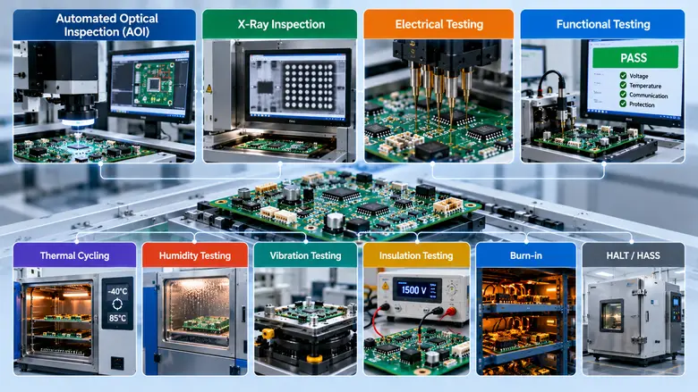
Burn-in or other reliability screening may be useful for selected products, particularly during new product introduction or significant design changes. HALT and HASS can also support reliability programs when well-planned, but they are not universal production requirements. Plus, manufacturers should define test coverage and acceptance limits before production.
10. Traceability and Documentation
When a field failure occurs, manufacturing records help identify its cause and determine whether other boards may be affected.
Useful traceability information includes:
- Component lot numbers and PCB batches
- Assembly revisions and process records
- Inspection and functional test results
- Firmware versions and calibration data
- Rework and repair history
Documentation also supports engineering reviews and system-level compliance work. However, good workmanship on the board doesn’t certify the full battery system, so BESS PCBA manufacturing records are more like feeding into a larger compliance picture.
Bottom Line
Reliability on a BESS board gets built in at every step, whether it’s insulation spacing in the layout or the burn-in data in the batch file. When you evaluate a manufacturer, ask how they handle high-voltage spacing, thermal profiles on heavy copper, coating, and traceability on power boards. Ask for examples of similar work. A supplier with real BESS PCBA manufacturing experience will answer those questions with specifics.
LHD Tech provides PCB fabrication and assembly services for industrial and other demanding electronic applications. Our capabilities include multilayer and heavy-copper PCB manufacturing, component sourcing, SMT and through-hole assembly, and turnkey manufacturing services.
We also support design-for-manufacturing reviews, prototyping, and PCB inspection and testing using methods such as AOI, X-ray inspection, and electrical testing.
For energy storage projects, these capabilities can support the production of battery monitoring/control and auxiliary circuit boards in accordance with approved customer specifications. Send over your PCB design files and let our engineering team recommend a build approach that fits your energy storage product.