Introduction
Every circuit in electronics is design to accomplish the same task: process, store, and transfer signal. But, how signal are manage and interpret defines the two great foundation of electronics — analog circuits and digital circuits. Understand the key differences between these form is crucial for student, engineers, or anyone interest in building, troubleshooting, or advancing circuit design today.
This detail guide compare how analog and digital circuits work, the role of analog signal and digital signal, and explain why certain circuit are best for some application. We’ll also cover how discrete signals and continuous signals are handle and explore practical design tip, modulation technique, and engineering challenge in both domain.
What is a Circuit? Understanding the Heart of Electronics
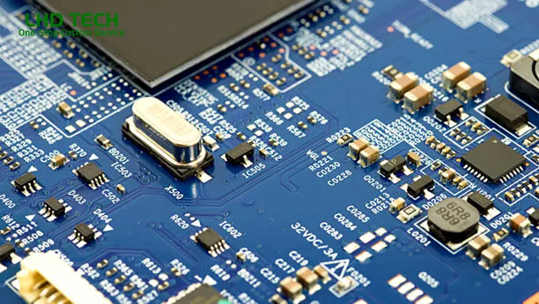
A circuit is a closed path through which electric current flow, connecting electronic component such as resistor, inductor, diode, transistor, or operational amplifier to perform specific task. Circuit are found everywhere—from a basic flashlight to sophisticate digital ICs and analog radio receiver.
Circuits process either continuous signal (analog) or discrete/binary signals (digital), with each approach having unique strength in different electronic system.
Analog and Digital Circuits: Overview and Key Differences
Analog and Digital: Definition
Analog Circuit:Work with analog signal—voltage or currents that vary smoothly and have an infinite number of value within a range.
- Digital Circuit: Handle digital signal—represent information with discrete state, typically 1 or 0, corresponding to high voltage or low voltage.
Key Differences
The key differences between analog and digital circuits come from how they interpret and process the world:
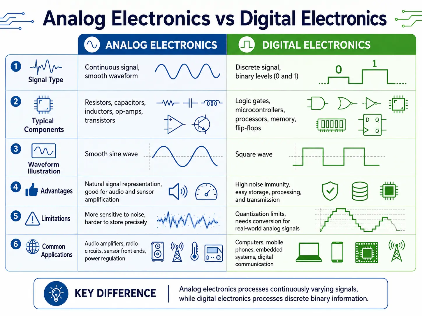
| Aspect | Analog Circuits | Digital Circuits |
| Signal Type | Continuous, infinite value (analog signal) | Discrete (digital signals), 1 or 0 |
| Common Task | Amplification, filter, modulation | Computation, control, data storage |
| Component | Transistor, resistor, capacitor, op-amps | Logic gate, flip-flop, digital ICs |
| Susceptible to Noise? | Yes, especially at low signal level | No, generally immune to minor disturbance |
| Signal Processing | Real-time, inherently analog | Sequential, combinational, binary logic |
| Error Detection/Correction | Difficult to design, significant error when being processed | Built-in error detection & correction possible |
| Typical Use Case | Audio, sensor, analog audio, battery charger | CPUs, memory, microcontroller, DSP |
| Circuit Complexity | Complex for precision, analog circuit design is an art | Easier to design, scalable, programmable |
Analog Signal and Analog Circuit Design
What is an Analog Signal?
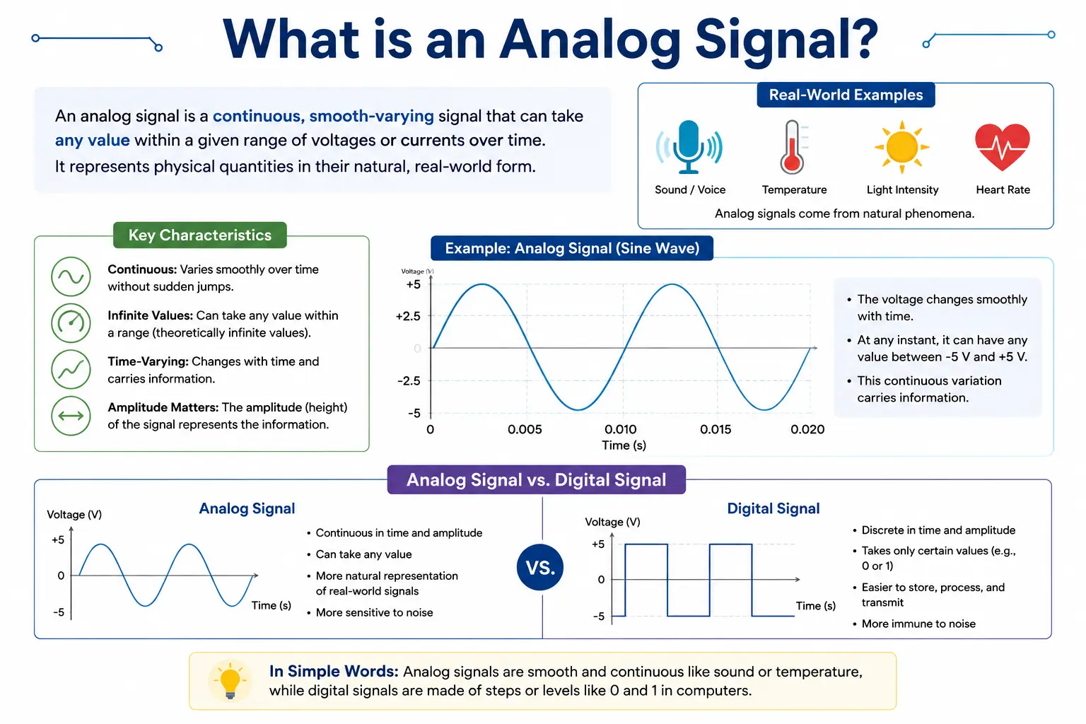
An analog signal is a continuously variable voltage that can reflect the real physical world—such as temperature, sounds, or light intensity. Analog circuitry is design to amplify, filter, modulate, and process these signal in real time.
Analog Circuit Design Fundamental
Analog circuit design demands precision in layout and component selection due to its susceptibility to noise, parasitic elements, and thermal effect. Engineer must carefully manage the voltage level of an analog signal, minimizing high-frequency interference and controlling feedback path.
Common component in analog electronic:
- Resistor
- Capacitor
- Inductor
- Transistor (analog amplification)
- Operational amplifier (op-amp)
- Diode (clipping, rectification)
Example: Design an Analog Radio Receiver
A classic analog radio receiver use an analog circuit for tuning, filter, and amplifying incoming RF signal. It might include:
- RF amplifier (transistor-based or op-amp)
- Bandpass filter (L-C filter)
- Modulation and demodulation circuit
- Audio amplifier (analog signal processing)
Such a circuit offer excellent real-time processing but may produce significant error if shielding, ground, and component tolerance are not optimized.
Digital Signal and Digital Circuit Fundamentals
What is a Digital Signal?
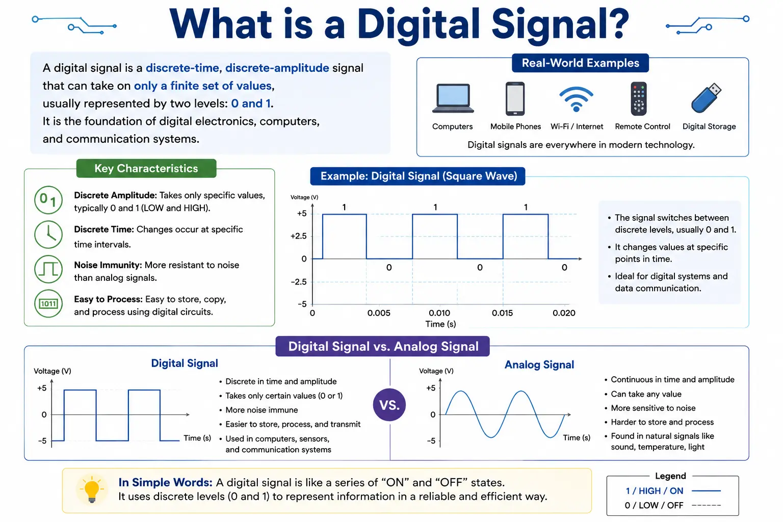
A digital signal is a series of discrete voltage level—typically only accepting two state (high and low). Digital circuit process discrete signals by represent data in the form of binary code: 0s and 1s.
Digital Circuit Design
Digital circuitry rely on robust, error-tolerant technique:
- Logic gate(AND, OR, NOT, NAND, NOR)
- Sequential logic circuit(flip-flops, register)
- Combinational logic circuit(adder, multiplexer)
- Digital ICs(microcontroller, FPGAs, processor)
Thanks to the discrete nature of digital signal, digital circuit are easier to design for complex tasks and are less susceptible to noise.
Analog Electronics vs Digital Electronics: Applications
Analog Electronics
- Audio Amplifier: High-fidelity analog signal processing for music and voice.
- Analog Battery Charger: Control charging current/voltage use continuous signal feedback.
- Sensor Interfaces: Read analog output from temperature, pressure, or light sensor.
Digital Electronics
- Microcontrollers and Computers: Store and process digital data and run complex logic.
- Data Storage Devices: Use digital circuitry for precise, non-volatile memory access.
- Sequential Logic Controllers: PLCs and embedded system using both combinational and sequential digital circuit.
Circuits Built with a Combination: Mixed-Signal
Most modern system are mixed-signal circuit, combining analog input (sensors, microphone) with digital processing (MCUs, DSPs) and analog output (amplifier, actuator).
How Circuits Process Signals: From Discrete to Continuous
Analog circuits process continuous signal, handling even the smallest fluctuation, while digital circuits process discrete signal, switching rapidly between two well-defined voltage level.
Example:
- High voltage = “1” (logic high)
- Low voltage = “0” (logic low)
Process an analog voice signal into a digital phone call require analog-to-digital conversion; the data is store and transmit as digital signal, then converted back for playback.
Fundamental Electronic Component in Circuits
Every circuit—whether analog, digital, or mix—include fundamental electronic component that determine how signal are process. Understand their role is key to mastering both analog circuit design and digital circuitry:
- Resistor: Controls the flow of current and sets voltage levels, key for both analog signal shaping and setting logic thresholds in digital circuits.
- Capacitor: Blocks DC while allowing AC signal to pass—vital in filtering analog signal and smoothing out noise in digital power supply.
- Inductor: Store energy in magnetic form and is commonly use in analog filter, RF circuit, and as part of switch-mode power supplies.
- Diode: Ensure current flow in only one direction, used for rectifier, signal demodulator, and for protecting sensitive digital component from voltage spike.
- Transistor: Can function as an amplifier (in analog circuits) or as a switch (in digital circuit), and is the building block for both analog and digital ICs.
- Operational Amplifier (Op-Amp): A versatile integrate circuit foundational to analog electronic—used in amplifier, filters, oscillator, and analog signal processing task.
Each components may be used differently: for instance, a transistor in an analog amplifier circuit function in its linear region, while in a digital circuit it’s used as an on/off switch for binary logic operation.
Analog-to-Digital and Digital Modulation
Analog-to-Digital Conversion (ADC)
To bridge analog and digital domain, an analog-to-digital converter (ADC) sample the continuous signal and translate it into a series of binary values that digital circuit can store and process. This is essential for systems need to digitize analog audio, sensor data, or image.
Digital-to-Analog Conversion (DAC)
Conversely, a digital-to-analog converter (DAC) takes binary digital data and recreates a smooth, analog signal—necessary for digital audio player, display, and control system that interact with real-world actuator.
Modulation Techniques
- Analog Modulation: Techniques such as AM/FM are used to transmit analog audio or RF signal over distance. These are inherently analog but may be processed digitally in modern radio.
- Digital Modulation: Techniques like QAM, PSK, and FSK encode digital data for reliable transmission over analog medium.
Analog Circuit Design vs Digital Circuitry: Practical Examples
Design Example 1: Analog Battery Charger
An analog battery charger uses analog circuitry to sense the voltage of a battery, apply precise charging current, and stop or reduce current when the battery reaches full charge, analog circuit are especilly effective here because the charging profile must follow a continuous voltage curve to ensure battery health.
Design Example 2: Digital Data Logger
A data logger for environmental monitoring might consist of:
- Analog front end: Reads signals from temperature, humidity, and pressure sensors
- ADC: Converts analog signals to digital
- Digital circuit: Microcontroller process, store, and timestamp the discrete digital data for later retrieval
Design Example 3: Analog Audio Signal Path
An audio amplifier circuit start with an analog microphone, passes through analog filters and operational amplifiers, before being processed by a digital equalizer (DSP), then converted back to analog by a DAC for output to speaker.
Design Example 4: Modern Sequential Logic Circuit
A microcontroller’s internal architecture use combinational and sequential logic circuit—built from millions of transistor—storing and manipulating digital data with precise voltage level and clock synchronization, the handling tasks from basic logic calculation to complex algorithm execution.
Key Differences Between Analog and Digital Circuits (Comparison Table)
| Feature | Analog Circuit | Digital Circuit |
| Signal Type | Continuous signal (infinite value) | Discrete/binary signal (two state: 1 or 0) |
| Main Processing Method | Voltage/current variation | High/low voltage logic (digital component) |
| Susceptibility to Noise | Highly susceptible to noise and interference | Strong noise immunity due to threshold |
| Error Detection & Correction | Difficult to design, significant error possible | Easier to design, error detection available |
| Modulation | AM, FM, inherently analog | Digital modulation (QAM, PSK, FSK) |
| Fundamental Electronic Components | Diode, transistor, op-amps, inductor | Logic gate, flip-flop, digital ics |
| Storage and Processing | Not suitable for large-scale storage | Can readily store and process digital data |
| Example Applications | Audio amplifiers, battery chargers, RF receivers | Computers, digital data loggers, embedded MCUs |
| Circuit Complexity | Precision analog circuit design is difficult | Digital circuits scale efficiently |
Real-World Tip: When you need precision, real-time response, and smooth control, analog circuit design excels, for storage, logic, and efficient communication, digital circuitry dominate.
Design Tips for Mixed-Signal Electronics
Circuit built with a combination of analog and digital section (mixed-signal) are the standard in modern electronic, but they bring unique challenges:
- Always separate analog and digital ground planes; connect at a single point only.
- Keep analog traces away from high-speed clock lines to reduce noise and crosstalk.
- Use shield enclosures and guard rings for sensitive analog section.
- Employ ferrite bead on power lines serving both analog and digital circuitry to filter out switching noise.
Error Detection, Correction, and Signal Integrity in Circuits
Analog Error Management
Analog circuit may produce significant errors when being processed due to susceptibility to noise, component drift, and supply fluctuations; careful analog design with feedback, shield, and component selection help, but some error are inevitable.
Digital Error Detection & Correction
In digital circuit, the discrete nature of digital signal allow designer to easily include parity check, CRCs, and other error detection/correction mechanism—critical for digital data integrity in storage, transmission, and computation.
FAQs on Analog and Digital Circuits
Q1: Why are analog circuits more susceptible to noise?
Because every small fluctuation in voltage level can change the analog signal’s information,the challenge for analog signal process, and especially at low signal strength.
Q2: Can a circuit accomplish the same task using analog or digital methods?
Yes,in principle, you can design the circuit (such as filters or controllers) in either domain;but ease of implementation, scalability, and accuracy often favor one approach over the other.
Q3: What’s a practical example of analog-to-digital in action?
The home thermostat sense temperature (analog), converts that into a digital signal for processing, then output a control signal to an HVAC relay—use both analog and digital circuit.
Q4: When is analog circuit design still preferred?
The application require real-time analog audio, high-fidelity radio, or exact physical signal reproduction still demand analog circuitry for the best performance.
Conclusion: Why Analog vs Digital Circuits Matter in Modern Electronics
In today’s electronics, the debate of analog vs digital circuits is more relevant than ever, as sensor-rich, connected devices proliferate, engineers need to choose the right approach for every application:
- Analog circuit remain unmatched in fidelity and real-world interfacing, processing an infinite number of values across continuous signal. Critical for sensor conditioning, audio amp, and RF.
- Digital circuits are the backbone of modern electronic—efficient, immune to noise, scalable, relying on binary, discrete signal and powerful logic. Perfect for data storage, control, and computation.
- Most advanced device are now a blend—a hybrid of analog circuit design and digital circuitry, maximizeperformance, flexibility, and resilience.
Focus on application need: Use analog for precision and real-time, digital for programmability and error management. The artful combination in mixed-signal design is the key to the future of circuit engineering.
Featured Snippet: Analog vs Digital Circuits — Quick Guide
What is the key difference between analog and digital circuits in electronics?
- An analog circuit processes continuous signals with infinite possible values, reflecting real-world variations (sound, light, temperature). Analog is highly precise but more susceptible to noise.
- A digital circuit processes discrete signals, using two states (1 or 0) for fast, reliable computation, storage, and transmission—strong noise immunity, easier scaling, built-in error detection.
- Most modern electronic circuits use a combination of both, with analog front-ends, digital processors, and robust analog-to-digital and digital-to-analog conversion.