New electronics require smaller size, greater speed, and enhanced reliability. This has made sophisticated PCB designs prevalent. Rigid Flex PCB and HDI PCB are two popular choices. The two assist engineers in creating small and high-performance products. However, they are not identical.
A Rigid flex PCB is employed when a board must bend, fold, or squeeze into a small size. A PCB with an HDI is adopted where a product requires additional parts in smaller areas. This guide provides an explanation of their differences, advantages, design considerations and their uses in simple language.
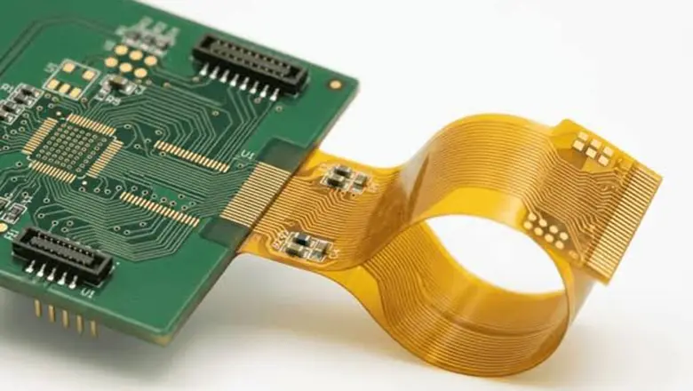
Understanding Rigid Flex PCB Technology and How It Works
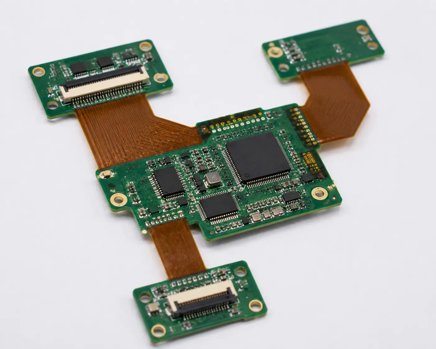
A Rigid Flex PCB is a combination of rigid board and flexible circuitry. Electronic components are mounted in the rigid parts. The spring like components bend or bend within the machine. This eliminates the use of additional cables and connections.
The rigid flex PCB is applied in small products where normal boards fail to fit. It is also more reliable since there is a reduction in the number of connectors that are weak. Medical devices, cameras, aerospace systems, wearables, and automotive electronics are typical applications of these boards.
HDI PCB Explained: Why High-Density Boards Matter Today
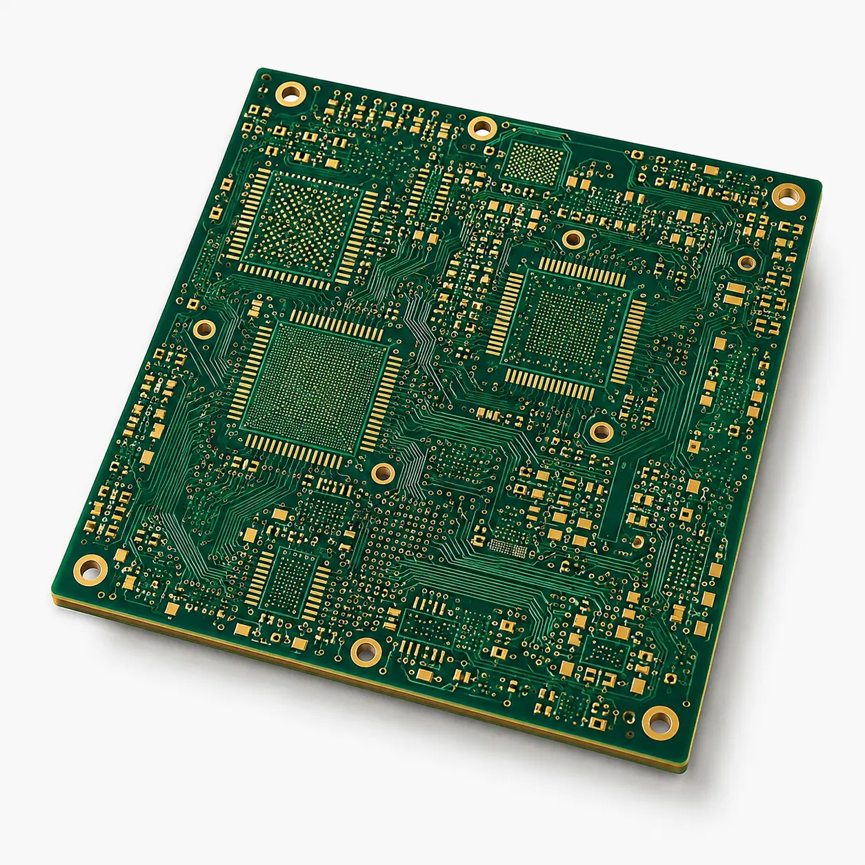
HDI PCB is shortened to High Density Interconnect PCB. It is created in such a way that it is able to fit more circuits and components in a smaller board space. HDI PCB involves microvias, blind vias, buried vias, thin lines and narrow spacing.
This PCB is utilised in devices that require small size and high performance. It is available in smartphones, tablets, laptops, 5G devices, medical electronics, and IoT products. HDI PCB is used to enhance routing, signal speed and board density. It is a powerful option when the standard PCB design is not able to accommodate the current miniature devices.
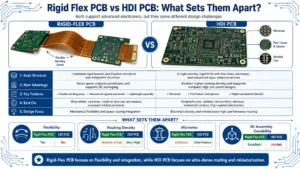
Rigid Flex PCB vs HDI PCB: What Sets Them Apart?
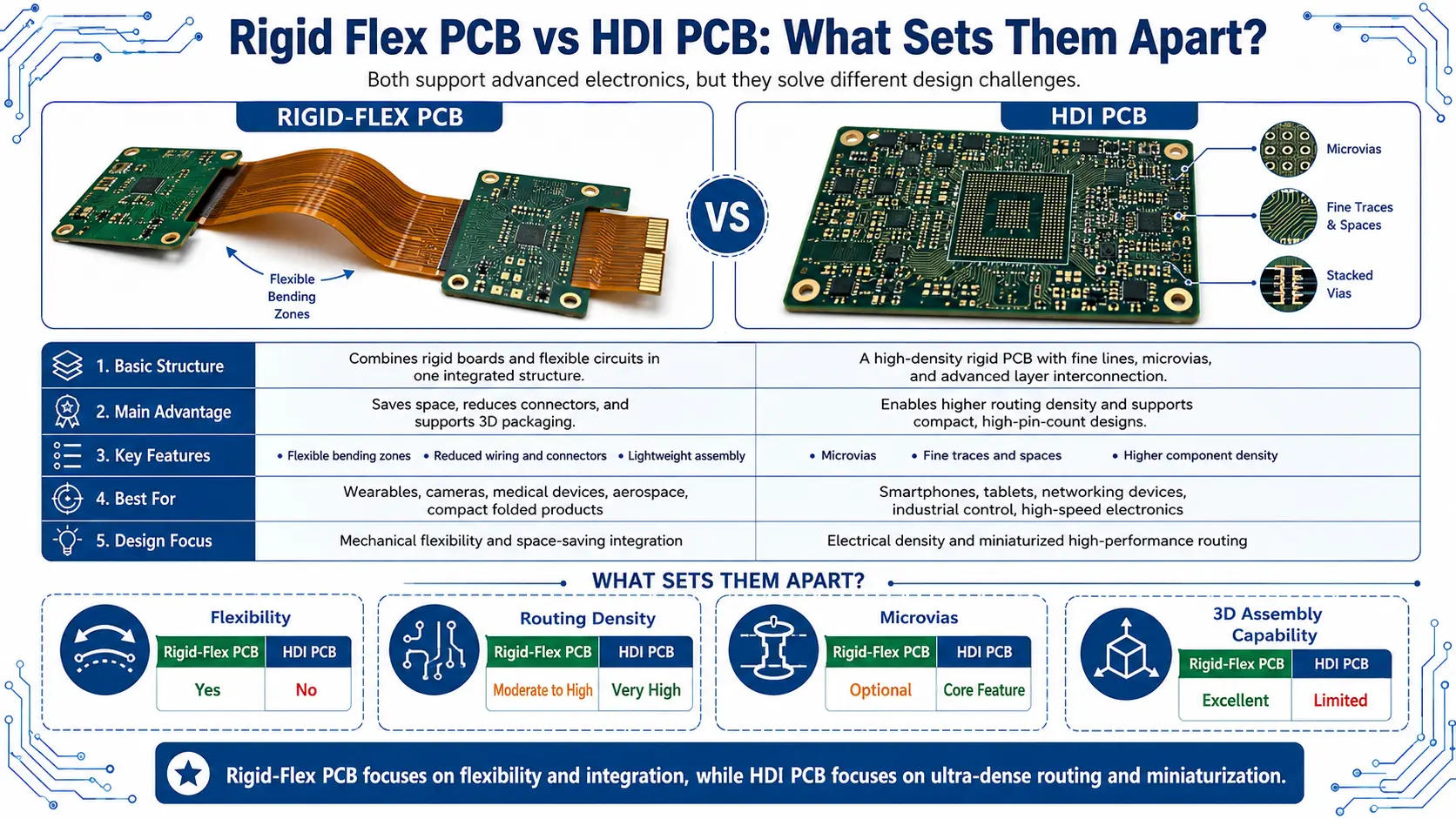
Their purpose is the primary distinction. Rigid Flex PCB emphasises product shape and flexibility. It enables the board to bend, fold and change wires or connectors. This renders it convenient for small and portable products.
HDI PCB is density- and routing-oriented. It assists in placing additional parts and interconnections on a smaller board. It is applicable in high-speed and miniaturised electronics.
Simply put, Rigid Flex PCB is a solution to mechanical design issues. HDI PCB is used to solve space and circuit routing issues. There are more advanced products that could use both technologies.
Why Engineers Choose Rigid Flex PCB for Modern Products
● Reduced Connectors for Better Reliability
A Rigid Flex PCB helps in minimising the quantity of connectors and cables within a product. Reduced connectivity translates to reduced failure points, leading to increased reliability and increased product life.
● Space-Saving Design
The flexible components enable the board to bend and fit into small or bizarre product shapes. This assists engineers in coming up with smaller and more efficient electronic devices.
● Lightweight Construction
Rigid Flex PCBs weigh less than conventional PCB assemblies that have multiple cables. This makes them ideal for drones, aerospace systems, medical devices, and portable electronics.
● Improved Durability
The boards are capable of sustaining vibration, shock and repetitive movement that is less than standard PCB assemblies. They can be used in harsh conditions where they need to be durable.
● Lower Maintenance Requirements
Maintenance is minimised since there are fewer moving parts and connectors. This assists in enhancing performance in the long-term and reduces maintenance costs.
Why HDI PCB Is the Preferred Choice for Compact Electronics
● Higher Component Density
HDI PCB provides additional routing space with microvias, blind vias and fine traces. This enables the use of more parts on a smaller board.
● Lighter and Smaller Products
The HDI technology assists manufacturers in designing small but lightweight electronic products without losing functionality or performance.
● Better Signal Performance
Reduced length of electrical paths minimises signal loss, interference, and noise. This enhances the work of fast and high-frequency electronic circuits.
● Supports Advanced Electronic Designs
HDI PCBs can be used with small-pitch BGAs, high-performance processors, and new chip packages in smartphones, medical equipment, and communications.
● Ideal for High-Performance Applications
HDI PCB technology is ideal in a product where miniaturisation is necessary, a faster method of transmitting data, a dependable electrical connection, and enhanced efficiency.
Best Practices for Designing a Reliable Rigid Flex PCB
Flex PCB design requires proper planning. The bend radius should be right. When the flexible part is too sharp, copper traces may break or break.
Designers are not supposed to put vias in bends. Curved edges are superior to sharp edges since they cause less stress. Appropriate materials should also be used in the flex area, including polyimide.
Stackup planning is vital as well. The rigid and flexible areas must work together without causing stress. It is best to work with the PCB manufacturer early. This assists in minimising design mistakes and manufacturing issues.
Essential HDI PCB Design Tips for Better Performance
Via and stackup planning is required in HDI PCB design. Microvias, blind vias and buried vias should be carefully placed. Ineffective via planning may add cost and decrease performance.
The line width, spacing, and signal paths are also to be considered by designers. Quick circuits must be properly impedance-controlled. Proper routing will minimise signal noise and loss.
Laser drilling and sophisticated manufacturing are commonly required with HDI PCB. Owing to this fact, design regulations should correspond to the capabilities of a manufacturer. DFAM early review is significant. It prevents redesigns, delays and additional costs.
Where Rigid Flex PCB and HDI PCB Are Used in Real-World Applications
Rigid Flex PCB is applicable in products where bending or folding is required, or compact packaging is needed. Typical applications are medical equipment, aerospace, cameras, wearables, car modules, and industrial machinery.
HDI PCB can be applied in products requiring high density and high performance. They are commonly used in smartphones, tablets, laptops, IoT sensors, 5G devices, automotive radar, and medical electronics.
Some products require both. To illustrate, a medical device that is to be worn might require flexible form and densely-routed circuit boards. Then, an HDI Rigid Flex PCB can be the most suitable solution.
Choosing the Right PCB Technology for Your Next Project
Rigid Flex PCB and HDI PCB are both significant in contemporary electronics. But they resolve different issues. Rigid Flex PCB is preferable when a board needs to bend, fold, or substitute cables. HDI PCB is optimal where a product requires additional components within a smaller area.
Rigid Flex PCB should be used in case your product requires flexibility and durability. When it requires density and high-speed routing, use an HDI PCB. HDI Rigid Flex PCB could be a suitable choice if it requires both.