Introduction to Rogers PCB Board Material
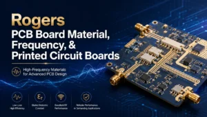
When it comes to high-frequency PCB and advanced RF and microwave applications, the choice of pcb materials will influence everything—from signal loss and impedance control to reliability and manufacturability. Among industry experts, the most trusted name is Rogers PCB board material.
Rogers PCB is a type of printed circuit board built using premium high-frequency Rogers material—laminates developed specifically by Rogers Corporation. These pcb materials are renowned for their ability to deliver a stable dielectric constant, low dielectric loss, and excellent thermal conductivity even at the highest frequency ranges.
In today’s PCB industry, the right material selection is a competitive edge. The use of Rogers PCBs is common in 5G, satellite, defense, advanced sensors, and automotive radar applications, where requirements are well beyond the capabilities of standard FR4. If you’re serious about RF, high-speed, or microwave PCB applications, understanding rogers pcb board material is key to unlocking superior circuit and system performance.
What Makes Rogers PCB Materials Unique?
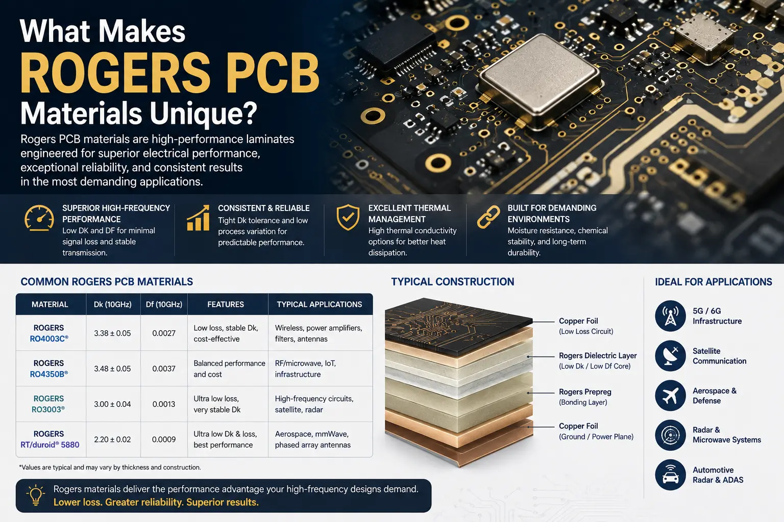
Rogers materials deliver as high-frequency laminates are engineered specifically for scenarios where pcb materials like FR4 fails. Leveraging advanced resin systems and ceramic-filling technology, these materials maintain low loss and stable dielectric constants across a wide frequency range; furthermore, their coefficient of thermal expansion matches that of copper foil, ensuring signal integrity in high-power, high-humidity, or extreme temperature-cycling environments. This is not merely an upgrade—it is a redefinition of the limits of durability.
Differences Between Rogers and Standard FR4
| Feature | Standard FR4 | Rogers PCB Board Material |
| Dielectric constant | ~4.3–4.8 (unstable, batch variation) | 2.2–11 (tightly controlled, frequency stable) |
| Dissipation factor (Df) | ~0.015–0.020 (moderate to high) | 0.0009–0.003 (low dielectric loss for high-frequency applications) |
| Signal loss | Significant at >2 GHz | Minimal even at mmWave frequencies (e.g. 77 GHz) |
| Thermal conductivity | 0.2–0.4 W/m·K | Up to 2.0+ W/m·K (greater heat dissipation) |
| Moisture absorption | 0.10–0.20% | 0.02–0.08% (low, stable performance in humidity) |
| Coefficient of thermal expansion (CTE) | 45–70 ppm/°C | 13–24 ppm/°C (close match to copper for better via reliability) |
| Application suitability | Digital, simple analog | High-frequency, RF, microwave, and demanding environments |
| Relative cost | Baseline | 3–8x higher (but delivers ROI in critical/high-frequency pcb) |
It is precisely the differences in the orders of magnitude regarding dielectric constant stability, dissipation factor, and coefficient of thermal expansion that make Rogers laminates the definitive choice for high-frequency pcb applications, mission-critical applications. In these scenarios, signal integrity, insertion loss, and resistance to thermal warping are not merely “ideal metrics”—they are the very reasons engineers choose Rogers.
Key Advantages of Rogers PCBs
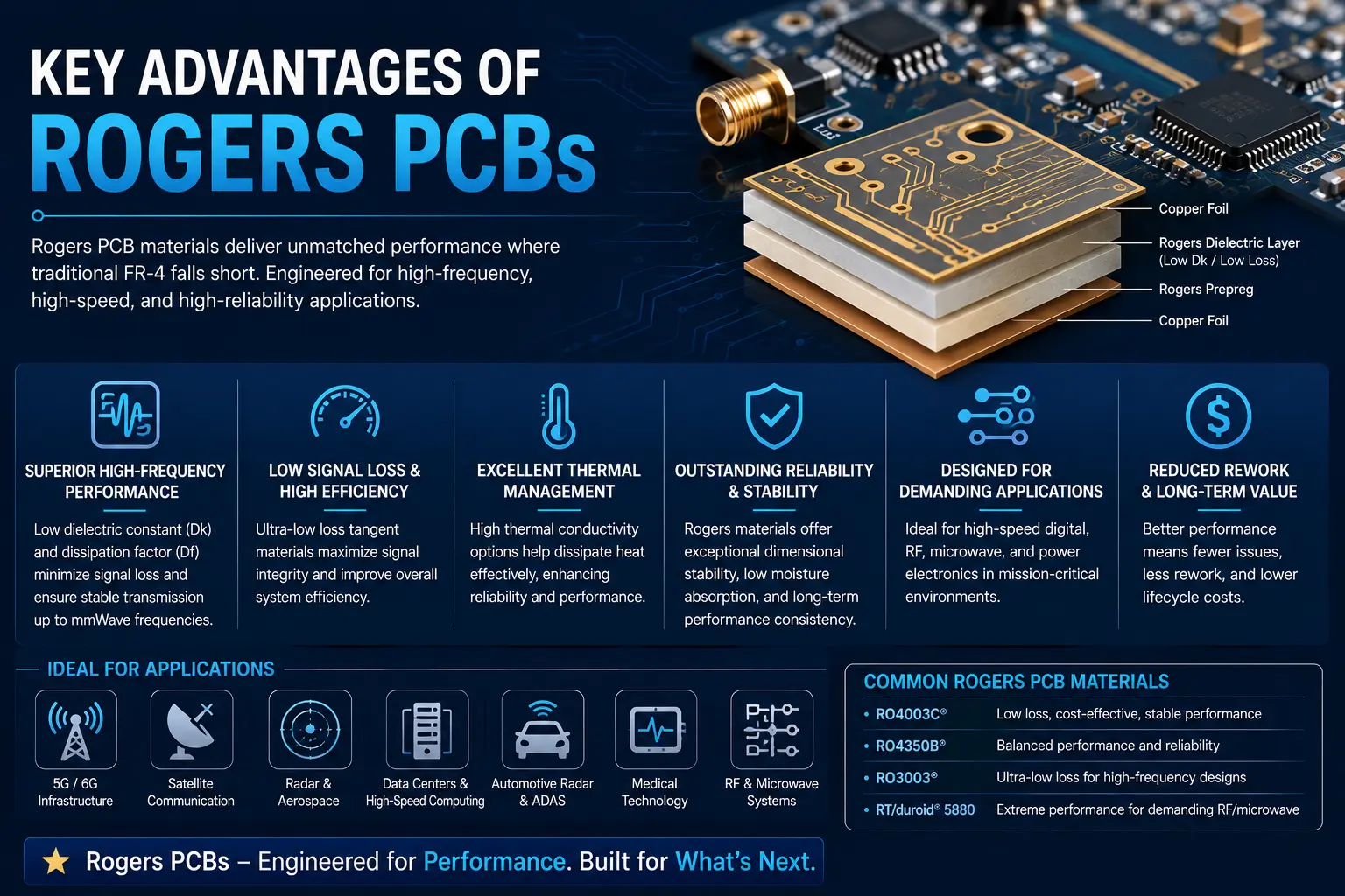
Rogers PCB board material is the gold standard for RF circuitry for numerous reasons:
1. Controlled Dielectric Constant and Dielectric Constant of Rogers PCB
Rogers laminates undergo rigorous process control regarding the dielectric constant (Dk), with typical batch-to-batch variation kept within ±0.05. This ensures a high degree of alignment between the design impedance control for microstrip lines or coplanar waveguides and the actual fabricated results, eliminating the need for iterative adjustments. For instance, the RO4000 series offers various grades with Dk values ranging from 3.4 to 3.7; these materials exhibit extremely low dispersion at frequencies up to 40 GHz, making them suitable for direct use in RF and microwave applications designs.
2. Ultra-Low Dielectric Loss
RT/duroid 5880 and RO3003 Rogers PCB materials feature a dissipation factor (Df) as low as 0.0009—more than 20 times lower than that of FR-4. In practical circuit links, this significantly eases the signal loss budget for a given trace length, allows for relaxed gain requirements in the final stages of high-frequency power amplifiers, and improves the system noise figure.
3. Superior Thermal Management
The Rogers boards material’s high thermal conductivity (e.g., 1.5 W/m·K for RO3003), combined with a Coefficient of Thermal Expansion (CTE) closely matched to copper foil (approx. 17 ppm/°C), ensures efficient heat dissipation from power devices while preventing fatigue cracking in vias and pads during thermal management cycling between -55°C and +150°C.
4. Low Moisture Absorption
With a typical water absorption rate of less than 0.03%, the material exhibits minimal drift in Dk and Df—even in environments with 85% relative humidity or condensation—eliminating the need to factor in a “humidity margin” during design. The dielectric constant remains stable during rapid temperature fluctuations, a critical attribute for RF and microwave applications.
5. Mechanical Strength and Reliability
A glass transition temperature (Tg) exceeding 280°C, combined with high Coefficient of Thermal Expansion (CTE), ensures that conductor pattern displacement remains within the micrometer range when Rogers substrates are subjected to reflow soldering, vibration, and operation across wide temperature ranges. Applications such as automotive radar, satellite transponders, and missile guidance systems mandate this performance metric as a critical screening criterion.
6. Easy Hybrid Stackups
By utilizing Rogers layers for high-frequency signal paths and FR-4 layers for digital logic and power distribution, functional partitioning is achieved within a single laminated structure. This combining Rogers and FR-4 design not only preserves the low-loss characteristics of the RF signal path but also keeps the overall material cost within 60% to 70% of an all-Rogers solution, while the interlaminar bond strength meets the requirements verified by standard peel tests.
Main Material Properties of Rogers PCB Board Material
Selecting pcb materials for high-frequency applications means understanding the core material properties and their direct impact on pcb design and RF performance.
Core Material Properties of Rogers PCBs
| Property | Rogers Range | Impact on PCB Applications |
| Dielectric constant (Dk) | 2.2 – 11 | Stable impedance, precise RF simulation |
| Dissipation factor (Df, loss tangent) | 0.0009 – 0.003 | Ultra-low signal loss for high-frequency pcb |
| Thermal conductivity | 0.5 – 2.0+ W/m·K | Efficient heat dissipation, essential for PA |
| Moisture absorption | 0.02 – 0.08% | Consistent freq. response in humidity |
| Tg (glass transition) | 200 – 280°C | Robust for high-temp reflow and assembly |
| Coefficient of thermal expansion (Z-axis) | 13–24 ppm/°C | Reliable vias, multilayer, and hybrid stackups |
| Outgassing | Exceptionally low | Required for aerospace, satellite, medical |
While Rogers PCB materials offer the baseline for high-frequency electrical performance, the true differentiators lie in three other dimensions: mechanical strength supports assembly and withstands vibration; thermal management determines power capacity and solder joint longevity; and environmental resistance ensures parameter stability in outdoor settings and across wide temperature ranges.
Types and Series of Rogers PCB Materials
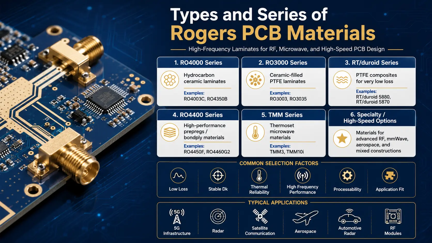
Rogers Corporation offers a vast portfolio of pcb materials tailored for every high-frequency application:
The Most Popular Rogers PCB Board Materials
- RO4000 Series(including RO4350B, RO4003C, RO4835):This series strikes a balance between impedance consistency, dielectric loss, and ease of processing; its lamination parameters are compatible with FR4 production lines, requiring no significant process adjustments. RO4350B has become a benchmark choice for high-frequency laminates in applications such as 5G base stations, communication backplanes, and radar detection.
- RO3000 Series(including RO3003, RO3006, RO3010):Featuring batch-to-batch dielectric constant stability and extremely low dissipation factors, this series excels in applications such as 24 GHz and 77 GHz millimeter-wave radar, ADAS sensing modules, and miniature filters. It provides a reliable material foundation for microwave PCBs requiring strict phase consistency.
- RT/duroid Series (including 5880, 6002, 6010):This series has long served as the reference material for ultra-high-frequency and mission-critical systems. The combination of ultra-low loss and extremely low moisture absorption meets the rigorous demands for long-term reliability and signal fidelity in aerospace electronics, missile guidance systems, and satellite transponders.
- TMM Series and CLTE-MW:Designed for chip antennas, miniaturized filters, and high-density multilayer stack-ups, these materials offer options for dielectric constant and coefficient of thermal expansion (CTE) to suit applications such as 5G millimeter-wave front-ends, precision RF measurement, and scientific instrumentation.
Highlight: Rogers RO4000 Series
The Rogers RO4000 series (including RO4350B, RO4003C, and RO4835) set the gold standard for scalable, high-frequency PCB design in industries needing a bridge between FR4 and PTFE’s advanced performance. RO4350B, in particular, is the go-to material for base station RF and PCB manufacturing where performance, cost, and processability must all be balanced.
Table: Comparison of Popular Rogers Laminates
| Laminate | Dielectric Constant | Dissipation Factor | Frequency Range | Thermal Conductivity | Key Application |
| RO4350B | 3.48 | 0.0037 | 1–40 GHz | 0.69 W/m·K | Telecom, 5G, radar, antennas |
| RO3003 | 3.00 | 0.0013 | 1–77 GHz | 0.5 W/m·K | mmWave, ADAS, automotive, satcom |
| RT/duroid 5880 | 2.20 | 0.0009 | 1–110 GHz | 0.2 W/m·K | Satcom, military, measurement |
| CLTE-MW | 3.00 | 0.0021 | 1–77 GHz | 0.5 W/m·K | Aerospace, chip antennas |
| TMM10i | 9.80 | 0.0020 | 1–110 GHz | 0.98 W/m·K | Miniaturized filters, mmWave |
Choosing the right Rogers material depends on your target frequency, required impedance control, signal loss budget, and the environment where your printed circuit board will operate.
Rogers PCB Board Material vs FR4
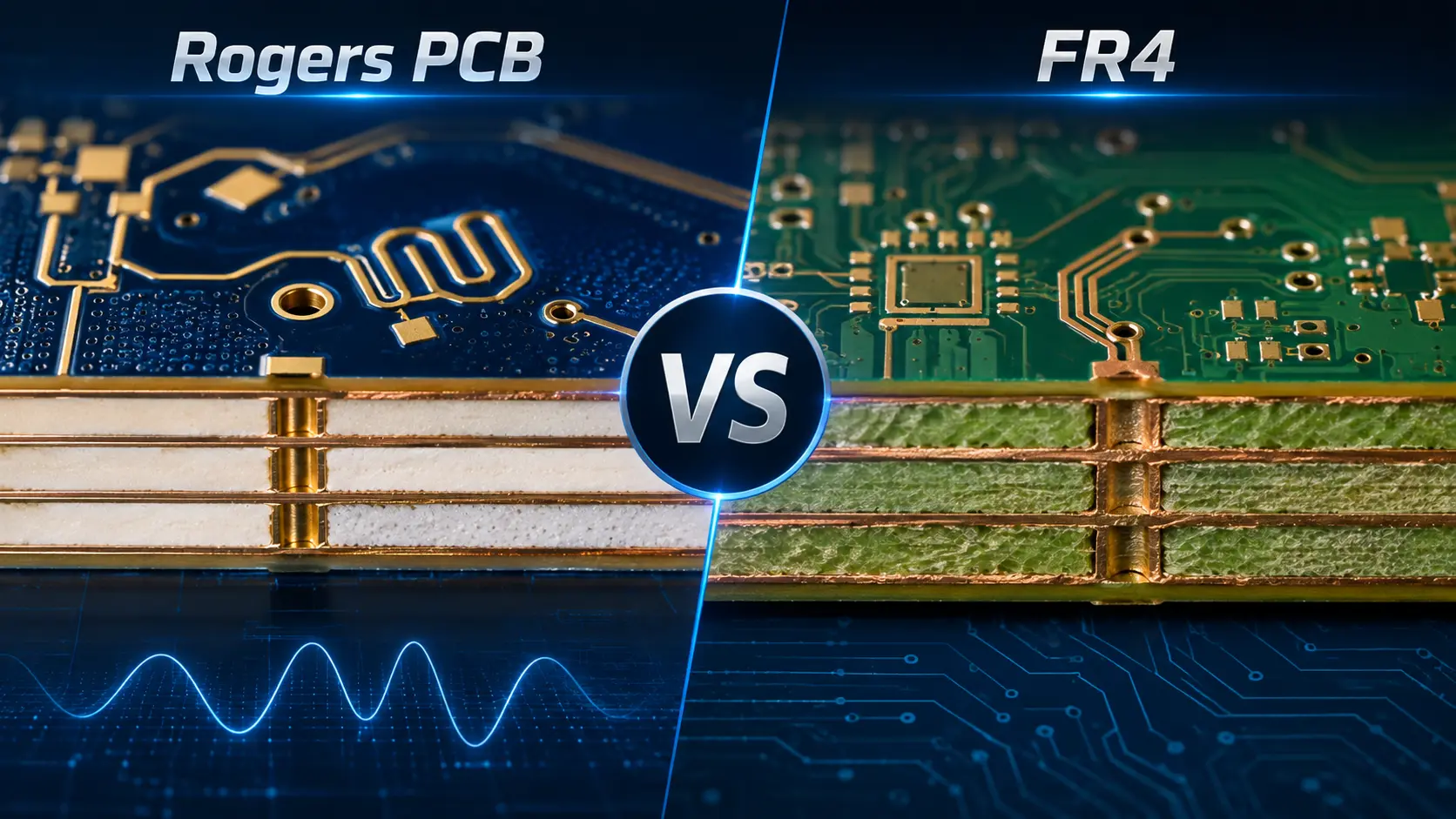
Engineers Choose Rogers When
Whenever high frequency pcb designs are involved, especially above 2 GHz, FR4 PCB materials start to exhibit high signal loss, unstable dielectric constant, and large variations in impedance control. This leads to unpredictable performance of the PCB, failed compliance, or excessive field returns.
Differences between Rogers and FR4:
- Rogers material laminates undergo rigorous in-line process control for dielectric constant (Dk), typically maintaining lot-to-lot variation within ±05, whereas standard FR4 materials can exhibit Dk fluctuations exceeding 10%.
- The llow dielectric loss of Rogers materials significantly reduces transmission line attenuation; for a given line length and high-frequency pcb, insertion loss can be tens of decibels lower than that of FR4.
- In projects involving mixed RF/digital or RF/power integration, utilizing Rogers layers for high-frequency signal paths and FR4 layers for logic and power distribution is a proven cost-control strategy. By optimizing interlayer adhesion and lamination temperature profiles, a product series compatible with standard FR4 manufacturing processes is achieved.
- FR4 is sufficient for control boards, power handling, or cost-critical consumer-grade boards with frequency <1 GHz.
FR4 vs Rogers: Quick Comparison
| Performance Area | Standard FR4 | Rogers PCB Board Material |
| Dielectric Constant | 4.3–4.8 (variable) | 2.2–11 (tight, stable) |
| Loss Tangent (Df) | 0.015–0.020+ | 0.0009–0.003 |
| Impedance Control | Good (<1 GHz) | Excellent (>1 GHz to mmWave) |
| Signal Loss | High (>2 GHz) | Low to ultra-low at all GHz |
| Thermal Management | Limited | Excellent |
| Cost | Low | 2–8x higher, but optimized in hybrid |
When and Why to Choose Rogers PCB Materials
Use Rogers Materials If:
- Your pcb design demands operation above 2 GHz, or especially for microwave PCB operating above 10 GHz or in the mmWave range.
- You need stable dielectric constant across temperature and frequency.
- Signal loss and phase integrity must be tightly controlled, such as in phased arrays, filters, or RF front ends.
- The board faces harsh environments—moisture, temperature cycling, or vibration.
- You’re building multilayer RF boards—Rogers PCB layers maintain impedance control and low loss across distributed stackups.
Choose Rogers Over FR4 When:
- Launching new products where first-pass success (right PCB) is essential (telecom, aerospace, automotive).
- Miniaturization or filter/antenna densification is critical—high-frequency material with higher Dk from Rogers means architects can shrink designs.
- Legacy FR4 designs hit a performance “wall” in terms of signal integrity, reliability, or compliance tests.
Applications and Industry Uses for Rogers PCBs
When it comes to powering the world’s most challenging pcb applications, Rogers stands alone:
- 5G/6G Base Stations: Massive MIMO, beamforming front-ends, and high-frequency signal distribution networks within transceiver units: Material loss and phase consistency directly impact system EIRP and sensitivity.
- Automotive Radar: 24 GHz blind-spot detection and 77 GHz long-range forward-looking radar modules impose strict requirements regarding the temperature drift of the dielectric constant and batch-to-batch consistency.
- Microwave Applications: Long-range point-to-point links, satellite transponders, and E-band (60/77 GHz) backhaul equipment: Loss budgets and linearity are primarily determined by laminate dielectric loss.
- Aerospace & Satellite: Telemetry transceivers, navigation signal sources, phased-array antennas, and deep-space transponders must meet requirements for outgassing rates, radiation resistance, and mechanical reliability across wide temperature ranges, in addition to electrical performance specifications.
- Medical: For MRI receive coil preamplifiers, RF ablation generators, and wireless monitoring patches, signal fidelity and power consumption directly impact diagnostic accuracy and device battery life; signal loss and Dk drift are both identified as critical risk factors.
- IoT & Sensing: Interference-resistant wireless nodes for mining sites, industrial plants, and urban infrastructure operate in industrial frequency bands and are deployed in non-air-conditioned outdoor cabinets; materials must withstand humidity and daily temperature cycling.
- Consumer Devices: For high-end Wi-Fi access points, active GPS antennas, and miniaturized wireless infrastructure—where the balance between manufacturing cost-effectiveness and high-frequency performance is a key consideration—hybrid laminates are commonly used.
Advanced Rogers PCB Design Tips and Manufacturing
Key Tips for Working With Rogers PCB Board Material
- Use Rogers PCB fabrication experts: Not all shops understand the unique needs of Rogers laminate drills, pre-treatments, or etching cycles.
- When using RO4000 series or similar, standard PCB manufacturing processes can be applied—helpful in prototyping or large-volume production.
- Thermal management starts in the stackup—don’t skimp on copper weights or prepregs between high-power and sensitive RF layers.
- Always specify test coupons for impedance control and validate results with a VNA or TDR.
- For hybrid stackups, make sure your manufacturer has experience combining Rogers layers and FR4 to prevent delamination.
Cost vs. Performance: Understanding the Cost of Rogers PCB
The True Cost of Rogers PCB Board Material
The cost of Rogers PCB is higher than FR4 PCB, sometimes by a factor of 4–8x in raw material price. However, it’s important to view this as an investment in RF, reliability, and manufacturability outcomes.
Typical Cost Drivers:
- Premium cost for the laminate or prepreg
- Specialized handling and tooling for rogers pcb fabrication
- Increased yield, fewer field failures, less need for board tuning or “touch-up”
Sourcing and Working With a Rogers PCB Manufacturer
Best Practices
- Work only with a PCB manufacturer proven in rogers pcb manufacturing, with documentation from Rogers Corporation, and a record of high-frequency projects.
- Material selection and stackup planning should be shared with your fab partner early—combine material expertise with design intent for a robust build.
- Confirm process certifications (IPC-4103, UL 94V-0, ISO, and, if needed, ITAR for defense) and authenticity of the Rogers core.
- Request performance samples, cross-section reports, and impedance testing on each build.
Expanded Case Studies and Real-World Examples
Case 1: 77 GHz Automotive Radar
- FR4 board failed in thermal cycling. Changing to Rogers 3003 erased field failures and met compliance on day one.
Case 2: 5G Base Station RF Board A leading telecom company was facing unacceptable signal loss and impedance drift with their FR4 PCB in next-gen 5G base station arrays. After switching to a hybrid stackup with Rogers RO4350B on RF and microwave layers and standard FR4 for digital control, they observed perfect phase alignment and a 40% reduction in assembly tuning time. The initial higher cost of Rogers PCB was offset within one quarter by reduced rework costs and faster product ramp-up.
Case 3: Satellite Communication Transponder Aerospace engineers needed to design a printed circuit board for a Ka-band transponder. The board had to survive vacuum, radiation, and dramatic temperature swings. Using RT/duroid 6002 for the RF and downlink circuits (thanks to its extremely low moisture absorption and coefficient of thermal expansion), the design passed all NASA outgassing and reliability tests. The performance of the PCB produced by Rogers beat previous generations using alternative substrate solutions.
FAQs About Rogers PCB Board Material
1. What is Rogers material in PCB?
Rogers high-frequency laminates are a family of substrate materials specifically designed for RF, microwave, and high-speed digital transmission applications. Key distinguishing features include: batch-to-batch dielectric constant (Dk) variation controlled within ±0.05; a dissipation factor (Df) more than an order of magnitude lower than that of FR4; and negligible drift in electrical parameters across the -55°C to +150°C temperature range.
2. What is Rogers 4350B material made of?
RO4350B belongs to the RO4000 series and is a thermoset laminate composed of hydrocarbon resin reinforced with glass fiber and filled with ceramic powder. Unlike PTFE-based materials, it can be directly laminated with standard FR-4 materials to form hybrid stacks without requiring special surface treatments.
3. What is the dielectric constant of Rogers 4350B?
RO4350B has a process dielectric constant (Dk) of 3.48 ± 0.05 at 10 GHz. Rogers also specifies a typical design Dk of 3.66 for circuit design.
4. What is the dielectric constant of Rogers RO4003C material?
RO4003C has a process Dk of 3.38 ± 0.05 at 10 GHz and a typical design Dk of 3.55. Its controlled Dk makes it suitable for RF and controlled-impedance PCB designs.
5. What is the dielectric constant of Rogers PCB material?
The dielectric constant depends on the specific Rogers material. For example, RO4003C is 3.38, RO4350B is 3.48, and RT/duroid 5880 is 2.20 based on their typical process Dk values.
6. What is the dielectric constant of Rogers RT5880?
Rogers RT/duroid 5880 has a dielectric constant of 2.20 ± 0.02 and a very low dissipation factor of 0.0009 at 10 GHz, making it suitable for microwave and broadband applications.
7. What is Rogers RT5880?
RT/duroid 5880 is a low-loss PTFE composite reinforced with randomly oriented glass microfibers. It is widely used in high-frequency, microwave, radar, and RF circuit applications.
8. What is duroid material?
Duroid is a Rogers family of high-frequency PTFE-based circuit laminates. These materials are known for low dielectric loss, stable electrical performance, and suitability for microwave and RF PCBs.
9. What is the thickness of the Rogers RT/duroid 5880 board?
Standard RT/duroid 5880 laminate thicknesses include 0.005, 0.010, 0.020, 0.031, and 0.062 inches (approximately 0.13–1.57 mm). Other thickness options may also be available.
10. What material is a PCB board made of?
Most standard PCBs use FR-4, a fiberglass-reinforced epoxy laminate. Rogers materials are typically selected instead when lower signal loss, tighter dielectric control, or better high-frequency performance is required.
Conclusion: Should You Use Rogers PCB Board Material?
Rogers PCB board material is unmatched for high-frequency, RF, and microwave PCB design. When the dielectric constant, low dielectric loss, and thermal conductivity of your substrate will define your system’s success, choose Rogers materials and partner with a pcb manufacturer who understands rogers pcb fabrication.
- For mmWave, radar, or 5G, always use Rogers PCB board materials for reliable, high-yield production.
- For high-reliability or hybrid PCB projects, combining Rogers and FR-4 allows you to use Rogers PCB only where it truly matters.
- Take advantage of material properties and the portfolio of popular Rogers laminates—from the process-friendly RO4000 series to next-level RT/duroid and ceramic substrates.
Engineers choose Rogers not just for performance, but for confidence—the assurance that what you build in the lab will work in the wild, in the sky, or in the data center.
Ready to get started?
- Contact a proven Rogers PCB board material expert and request prototype advice.
- Use Rogers’ online calculators and consult design support for choosing the right Rogers PCB material.
- Share your stackup, frequency range, and project goals early for DFM input.