
A security camera has to capture clear footage in bright daylight and again at 3 a.m., sometimes through heavy rain or freezing temperatures. Behind that performance is a printed circuit board assembly (PCBA) that manages imaging and power, along with night vision functions within a compact space.
The challenge is keeping a noise-sensitive image sensor close to infrared LEDs that generate heat and power converters that introduce electrical interference. Good security camera PCBA design addresses these issues and helps the camera maintain image quality and reliable operation.
This guide covers the key design requirements, including sensor signal routing, day/night switching, outdoor protection, and production testing.
What Is a Security Camera PCBA?
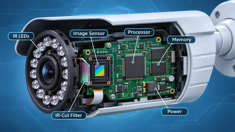
A Security Camera PCBA (Printed Circuit Board Assembly) is the assembled circuit board that connects and controls a camera’s electronic components. It usually connects the image sensor, image processor, memory, power management circuits, and communication interfaces. Cameras with infrared night vision also need circuitry to control the IR-cut filter and infrared LEDs.
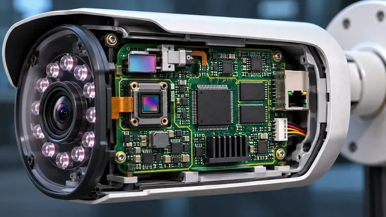
These components share a compact enclosure. So, there is little room for heat dissipation or electrical isolation. Therefore, every section of the layout requires careful planning because electrical noise and excessive heat can affect the final image.
Main Considerations for Reliable Security Camera PCBA Design
A reliable PCBA for security cameras requires careful planning across several areas. These include image sensor routing, day/night switching, infrared illumination, thermal management, and more. Each of these factors affects image quality and power efficiency under different environmental conditions.
1. Image Sensor Routing and PCB Layout
The image sensor captures the scene and sends image data to the processor, often through a MIPI CSI-2 interface. The processor handles image processing and video encoding before transmitting footage through Ethernet or Wi-Fi.
High-Speed Signal Routing
MIPI CSI-2 interfaces using D-PHY require differential routing with a nominal impedance around 100 Ω (depending on the devices and manufacturer specifications).
Engineers should control trace impedance and meet the required length-matching limits while avoiding unnecessary vias. High-speed signals also need continuous reference planes to reduce electromagnetic interference.
PCB layer count depends on routing density and the chosen components. A 4-layer PCB design may be sufficient for a simple camera, but a 6-layer PCB stackup provides additional routing space and options for power and ground planes.
Protecting Sensitive Sensor Circuits
Image sensors require stable supply voltages, especially on their analog power rails. Excessive ripple or interference can contribute to visible image noise and other performance problems.
Place decoupling capacitors close to the relevant power pins and keep high-current switching loops away from sensitive sensor circuits. A continuous ground reference helps control return currents.
2. Design Reliable Day/Night Switching
Security cameras must respond to changing light conditions without constantly switching modes. The printed circuit board controls this process through ambient light sensing and IR-cut filter movement, along with infrared illumination.
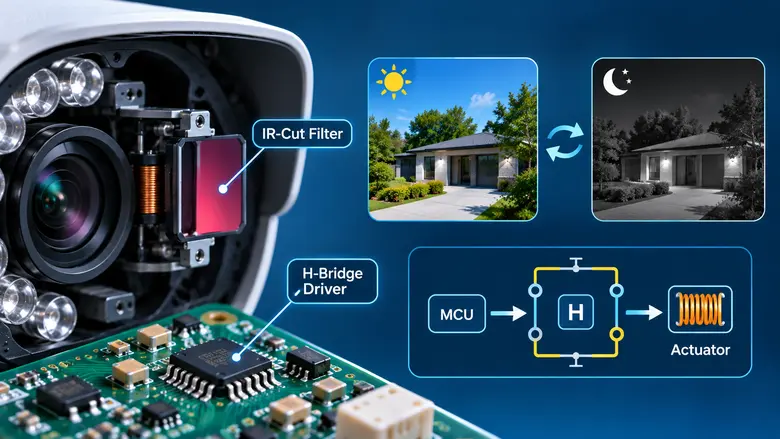
How the IR-Cut Filter Works
During daylight, the IR-cut filter blocks infrared wavelengths from reaching the image sensor to help preserve accurate colors.
As the scene becomes darker, the controller moves the filter out of the optical path and enables infrared illumination when needed. The camera usually switches to monochrome imaging to improve its ability to capture low-light scenes.
Many cameras use a latching electromagnetic actuator that moves the filter between two positions. A short electrical pulse changes its position and allows the actuator to remain in place without continuous coil power.
H-Bridge Driver Design
An H-bridge driver reverses the polarity across the actuator coil and makes the filter move in either direction.
The driver must handle the required pulse current and control switching safely. Suitable inductive voltage protection and shoot-through prevention are also important.
Engineers should verify filter movement at the lowest expected supply voltage and across the camera’s operating temperature range. An incomplete movement can leave the camera with incorrect daytime colors or poor night vision.
Preventing Frequent Switching
Passing headlights or shadows can cause sudden changes in brightness. A poorly configured light sensor may keep triggering the filter.
Separate day-to-night and night-to-day thresholds, known as hysteresis, help prevent this behavior. Firmware can also require the light level to remain beyond a threshold for a short period before switching.
3. Choose the Right IR LED Driver for Night Vision
Infrared LEDs illuminate the scene when visible light is insufficient. Their performance depends on wavelength selection, along with current regulation and thermal management.
850 nm vs. 940 nm Infrared LEDs
Two wavelengths are common in security cameras:
| Feature | 850 nm IR LEDs | 940 nm IR LEDs |
| Visible glow | Faint red glow | Little or no visible red glow |
| Sensor response | Generally higher | Generally lower |
| Illumination range | Often longer | Often shorter at comparable output |
| Common use | General surveillance | Discreet surveillance |
The final choice depends on the camera sensor’s infrared sensitivity and lens characteristics. The required viewing distance also influences the decision.
Why Constant-Current Drivers Are Crucial
Infrared LED forward voltage varies with temperature and manufacturing tolerances. Illumination can become inconsistent without proper current regulation, and LEDs may operate beyond their intended limits.
A constant-current driver helps maintain stable LED output. For arrays containing multiple LED strings, current balancing can improve illumination uniformity.
PWM dimming provides another level of control, as it allows the camera to reduce infrared brightness when full output is unnecessary. Engineers should also consider open-circuit/short-circuit and overtemperature protection.
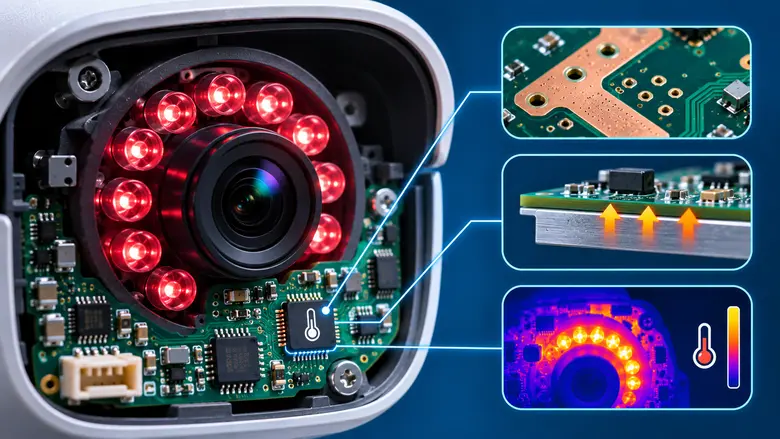
4. Manage Heat Around Infrared LEDs
Heat is a major concern in compact security camera PCBA designs, especially when infrared LEDs operate continuously throughout the night. High LED temperatures can reduce light output and accelerate component aging. Heat reaching the image sensor may also increase image noise.
For higher-power illumination arrays, designers can use larger copper areas and thermal vias. They can also use a separate metal-core PCB mounted to the camera housing to help transfer heat away from electronic components.
Temperature sensors can provide feedback for thermal protection or LED current reduction. Test the thermal performance with the camera fully assembled, since an enclosed housing can retain much more heat than an exposed prototype board.
5. Plan the Power Supply and Network Interfaces
Security cameras have changing power demands. The processor, image sensor, and network circuits operate throughout the day. Infrared LEDs and optional enclosure heaters add extra loads at night.
Power-over-Ethernet Requirements
Many IP cameras use Power over Ethernet (PoE) for data transmission and electrical power through one network cable. The available power depends on the PoE standard:
| PoE Type | Maximum Power Available at Powered Device |
| IEEE 802.3af, Type 1 | 12.95 W |
| IEEE 802.3at, Type 2 | 25.5 W |
| IEEE 802.3bt, Type 3 | 51 W |
Engineers should calculate the camera’s combined power demand at its highest expected load, while accounting for converter losses and startup conditions. For example, a camera operating during the day may experience a voltage drop when the IR LED array and heater activate together. An undersized power supply can cause unexpected restarts or unstable video transmission.
Ethernet and Wi-Fi Protection
Ethernet interfaces need appropriate differential-pair routing and protection against electrical disturbances. Outdoor designs may also require surge and electrostatic discharge (ESD) protection, with testing based on applicable standards such as IEC 61000-4-5 and IEC 61000-4-2.
Antenna placement needs attention for wireless cameras. Nearby metal structures and switching regulators or high-current traces can affect radio performance.
6. Protect the PCBA Against Outdoor Conditions
Outdoor security cameras face moisture, dust, temperature changes, and condensation. These conditions must be considered during both security camera PCBA design and enclosure development.
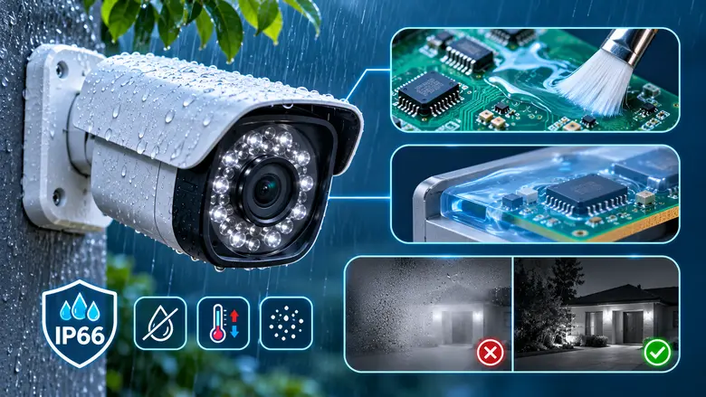
IP66 Enclosure Protection
IP66 is usually specified for outdoor security cameras. It indicates that a tested enclosure is dust-tight and protected against powerful water jets under defined test conditions.
The rating applies to the assembled enclosure, including its seals and cable entry points. It does not guarantee that the electronics inside will remain free from condensation.
Conformal coating can help protect exposed circuit surfaces from moisture. PCB potting may provide further protection for applications requiring additional encapsulation, although it can complicate repair and heat management.
Condensation and Infrared Reflection
Moisture accumulating inside the camera can fog the lens window and reduce image clarity. Some designs use controlled heaters to limit condensation, which must be included in the power and thermal budget.
Infrared reflection can create another night vision problem. Light reflecting from the front window, nearby surfaces, or dirt on the lens cover may produce bright patches in the image. Suitable optical shielding, with proper LED positioning and careful enclosure design, helps reduce unwanted reflections.
7. Security Camera PCBA Manufacturing and Assembly
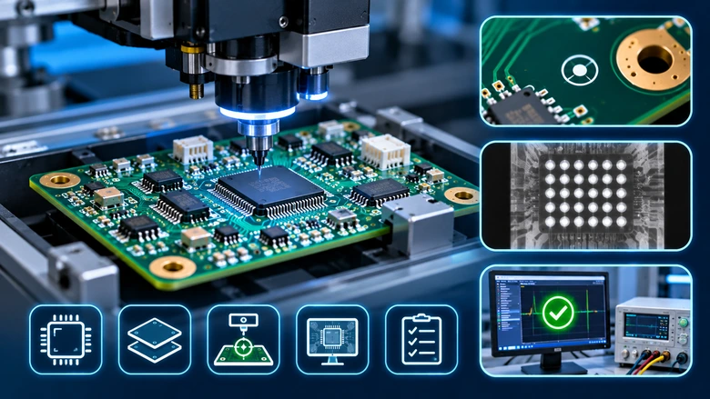
Security camera PCBAs usually contain fine-pitch processors and components mounted on both sides of the board. These compact layouts require careful planning to ensure accurate component placement and reliable soldering.
Designers should leave sufficient space for assembly equipment and potential rework, while considering the soldering sequence and each component’s temperature requirements. For boards with components on both sides, following proper double-sided PCB assembly practices helps reduce manufacturing defects. Well-positioned PCB fiducial marks also help automated placement machines align fine-pitch components accurately.
After being assembled, the boards need thorough inspection. Automated optical inspection (AOI) can identify visible soldering and placement defects. Similarly, PCB X-ray inspection helps detect hidden issues beneath BGA packages, such as solder bridges and voids.
Electrical and functional testing completes the process by verifying that the assembled PCB operates as intended, including issues that visual inspection alone cannot detect.
8. Test the Security Camera Under Real Operating Conditions
Testing should cover the camera’s actual working environment, especially nighttime operation when power consumption and heat generation may increase.
| Test Area | What to Check |
| Day/night switching | Correct filter movement and stable thresholds |
| IR LED driver | Current regulation and dimming/illumination |
| Thermal performance | Component temperatures under maximum load |
| Image quality | Sensor noise, color accuracy, and IR reflection |
| Power supply | Startup behavior and voltage stability |
| Network interface | Reliable Ethernet or Wi-Fi communication |
| Outdoor reliability | Condensation, sealing, and temperature cycling |
The most useful tests combine several operating conditions. For example, running the IR array at maximum brightness inside a sealed housing at the highest rated ambient temperature can reveal heat-related failures that basic bench testing misses. A short production trial using a fast prototype PCB process can help identify issues before larger manufacturing runs.
Conclusion
Reliable security camera PCBA design starts with careful sensor routing. Then it extends through day/night control and infrared illumination, along with thermal management. These decisions affect whether a camera delivers clear footage across changing light and environmental conditions.
Manufacturing quality matters just as much. LHD TECH provides PCB fabrication, component sourcing, SMT and through-hole assembly, along with AOI, X-ray inspection, and testing services. For security camera electronics projects, you can contact LHD TECH with your Gerber files and assembly requirements to discuss PCB manufacturing and prototyping.