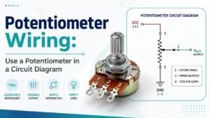
Introduction to Potentiometer Wiring
The humble potentiometer is one of the most important, flexible, and widely used component in electronic circuit. Whether you’re adjusting the volume of an audio amplifier, dimming light, calibrating sensor, or fine-tuning analog device, potentiometer deliver unmatched control.
But to get reliable result, the way you connect a potentiometer—from identifying each pin and terminal to interpreting the effect of the wiper position in your circuit—matter enormous. Good potentiometer wiring isn’t just about follow a datasheet; it’s about understanding how every wire, solder joint, and circuit diagram decision impact long-term performance, noise, and user experience.
In this in-depth articles, you’ll learn not only the fundamental theory behind potentiometer but also see practical potentiometer wiring example, detailed circuit diagrams, troubleshooting advice, and expert tips for both analog and digital application, including Arduino and audio equipment.
What is a Potentiometer? (Definition, Structure, and Purpose)
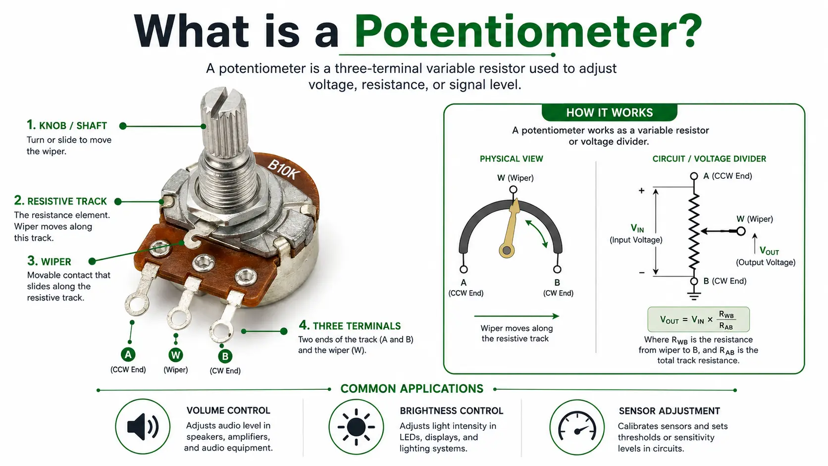
A potentiometer is a type of variable resistor with three terminal and a moving contact call the wiper. Its main role is to provide variable resistance or to act as a manual voltage divider in the circuit. Inside the potentiometer, the resistive track (often carbon or cermet) is connect at two end, each with a terminal, while the wiper connects to the carbon strip at a specific point, providing a tunable voltage or resistance output.
Potentiometer Definition and Key Role
- Adjustable resistor: Use to finely set resistance in calibration, gain setting, or current-limiting role.
- Manual voltage divider: When all three pin are used, you split a supply voltage into two variable voltage—essential for tuning and control circuit.
- User-interface component: Allow easy, analog human interaction with electronic (e.g., turning a knob to adjust brightness).
Where Are Potentiometers Used?
- Audio device: Adjusting the volume, tone, or equalizer in audio amplifiers and mixing desks.
- LED circuits: Providing variable led brightness and dimmer effects.
- Industrial controls: Setting reference voltages, parameters, or calibrating sensors in PLC or instrumentation circuits.
- Embedded microcontroller systems: User input for menu navigation, setpoints, and analog testing.
How Does a Potentiometer Work? (Principle, Track, and Wiper Movement)
Understanding the working principle helps anyone use a potentiometer with confidence. The device operates using a resistive track with contacts at each end and a wiper that slides or rotates along the track, dividing the total resistance into two parts.
Potentiometer Working Principle
Voltage Divider Action: The main functions of most potentiometer circuit is to split the applied supply voltage across the two end terminal, allow the user to “tap” any desired output voltage at the point where the wiper contact the resistive strip.
Variable Resistor Mode: If only two pins are used (the wiper and one terminal), the potentiometer act as a variable resistor, controlling current flow in devices like LEDs or motors.
Track and Wiper Position:
- As the wiper moves toward the left pin, the resistance between the wiper and the left pin decreases while resistance to the right pin increases.
- Moving the shaft in one direction raises resistance between the middle pin and one end terminal while lowering it between the wiper and the other terminal.
- Adjusting the volume on audio equipment or changing the brightness of a lamp both use this core principle.
How Resistance Changes
Suppose you measure resistance between the wiper and the right pin with a multimeter:
- Turn the knob clockwise, and resistance between the wiper and the right pin drops toward zero, while resistance between the wiper and the left pin increases toward maximum.
- Move along the track, and these values change “in opposition.”
This continuous change allows not only fine volume adjustments and sensor setpoints but also real-time human control in all types of circuits.
Pinout: Understanding the Three Terminals of a Potentiometer
A classic potentiometer has three terminal: two at either end of the resistive track and one attach to the wiper. Understanding which pin is which is vital—miswiring these is a leading cause of circuits failure.
| Pin Number | Name | Usual Role | Notes |
| Terminal 1 | Left pin | GND or Reference | Start of track (CCW or “counterclockwise”) |
| Terminal 2 | Middle pin | Wiper/Output | Tap point; supplies VARIABLE voltage |
| Terminal 3 | Right pin | VCC/Signal Input | End of track (CW or “clockwise”) |
How to Identify the Pins of a Potentiometer:
- The middle pin always connects to the wiper.
- Meter between outer pins: should read the rated total resistance (like 10kΩ).
- As you turn the knob, measure resistance between the left pin and the wiper or wiper and the right pin—this value will change from near zero up to the max resistance.
Types of Potentiometers and Their Applications
Potentiometer Types Explained
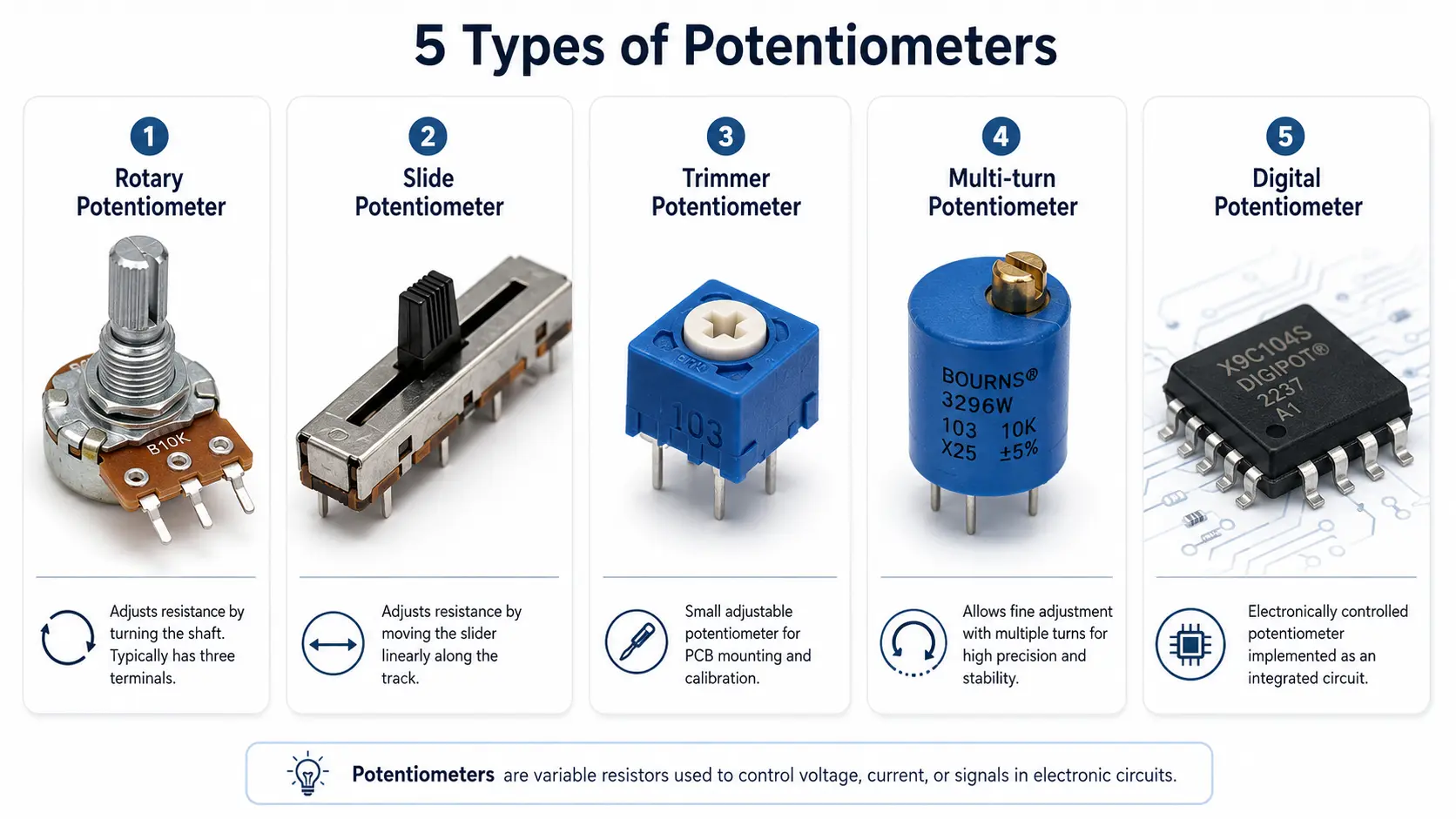
Understanding the different potentiometer type, each with their own wiring pattern, mounting arrangement, and atmosphere of use, help you choose the right control for your application.
Rotary potentiometer: The most common type, operated using a knob on a rotating shaft. Use for volume control and all sort of front-panel adjustment. Inside the potentiometer, the wiper rotate across the resistive track as you turn the knob.
Slide potentiometer: Here, the wiper moves along a straight resistive track. Often found in audio mixers or equalizers for linear, visual control.
Trimmer potentiometer: Small adjustable devices, typically adjusted using a small screwdriver on PCBs and adjusted during manufacturing or servicing. A trimmer potentiometer is ideal for factories calibration.
Multi-turn potentiometer: Feature a screw-type wiper, requiring several full rotations for a complete sweep. These deliver precise adjustment and are used in test equipment, instrumentation, and calibration.
Digital potentiometer: Unlike the classic variable resistor, a digital potentiometer is a chip controlled by digital signals (such as SPI or I2C) and can be programmed by a micro controller or other digital logic. It acts like a variable resistor or voltage divider but with settings changed electronically, making it perfect for remote adjustment or automated tuning in electronic circuits.
Potentiometer Types
| Potentiometer Type | Movement | Typical Use | Example | Notes |
| Rotary potentiometer | Rotating | Volume control, brightness, tuning | ALPS RK09K | Knob operated, standard for audio devices |
| Slide potentiometer | Linear slide | Audio faders, lighting consoles | Panasonic EVJ | Sweeps in a straight line |
| Trimmer potentiometer | Screwdriver | PCB adjustment, calibration | Bourns 3296 | Small, for rare/precision settings |
| Multi-turn trimmer pot | Screwdriver | Test/lab equipment | Vishay 64W | Allows very fine resistance tuning |
| Digital potentiometer | No physical | Programmable/automation | AD5206 | Adjusted by digital signals, MCU-friendly |
A potentiometer is a type of adjustable resistor essential in both simple and sophisticated electronics, making the correct understanding of each design key to optimal performance.
PCB Design, Mounting, and Soldering Guidelines
Correct mounting and solder technique are crucial for potentiometer reliability, whether connections are made directly to a circuit board or via wires in a larger assembly.
Best Practices
- Use manufacturer’s recommended PCB footprint, especially for SMD parts.
- Support panel-mounted pots mechanically—never rely on solder joints alone for long-term strength, especially when the knob experiences frequent rotation.
- For through-hole types, maintain adequate pad size and thermal relief for optimal soldering.
- Solder quickly and cleanly—excessive heat can damage the resistive track or melt the housing.
- For trimmer potentiometer applications, calibrate after board cleaning and lock the setting (with lacquer or glue) for stability.
- Remove flux after soldering, especially for high-impedance analog circuits, to prevent leakage.
Mounting Trimmers
- On PCBs and adjusted using a small screwdriver, the middle and bottom pins (or any two pins on a multi-turn pot) may be chosen for best accessibility or minimal trace length.
Troubleshooting Potentiometer Wiring and Circuit Issues
Every electronics designer will eventually face faults requiring troubleshooting potentiometer wiring. Here are classic symptoms, diagnoses, and fixes:
Common Issues & Solutions
| Issue | Cause | Solution |
| Output voltage stuck | Broken wiper contact | Replace potentiometer, check wiper pin continuity |
| Output jumps/discontinuous | Dust/dirt on resistive track | Clean with contact cleaner or replace |
| Scratchy audio/volume control | DC on potentiometer, poor grounding | Add AC coupling capacitor and ensure proper grounding |
| Unstable readings (MCU input) | Floating wiper, long wiring | Tie third pin to the middle pin, use buffered input |
| Pot gets hot | Too low resistance value, overload | Check resistance value and power rating, replace |
| No effect in adjustment | Miswired pins | Verify pin mapping with datasheet and DMM |
Pro Tip
Measuring the resistance between the left pin and the wiper and between the wiper and the right pin while turning the shaft is the best way to verify a healthy potentiometer in and out of a circuit.
Advanced Potentiometer Design Tips and Embedded Applications
Circuit Enhancements
- Buffer the wiper with a unity-gain op-amp voltage follower if analog signal stability is essential, especially before sensitive ADCs.
- Implement star grounding and guard traces to reduce noise in audio and mixed-signal applications.
- In stereo equipment, use dual-gang rotary potentiometers for independent left and right channel volume adjustments.
Using a Digital Potentiometer
A digital potentiometer is a chip with a resistive array and wiper control by digital signal. Integrate easily with microcontrollers for programmable gain, offset, or calibration. Always decouple the supply pin of digital pot and ensure their reference voltage and logic level match your circuit.
Preventing Dead Zones
When using only the wiper and one side pin, short the third pin to the middle pin for reliability, minimizing open-circuit risk if contact is lost.
Frequently Asked Question About Potentiometer Wiring
1. How do you wire a 3-pin potentiometer?
Connected the two outer terminal across the input voltage or signal. Use the center terminal, called the wiper, as the adjustable output.
2. What are the three terminal of a potentiometer?
The two outer terminals connect to the ends of the resistive track. The center terminal is the wiper, which moves along the track to provide variable resistance or voltage.
3. How can you identify the pins on a potentiometer?
The center pin is usually the wiper. Use a multimeter to confirm: resistance between the two outer pins remains constant, while resistance from the center pin to either outer pin changes when the shaft turns.
4. Does it matter which way you wire a potentiometer?
Swapping the two outer terminals reverses the adjustment direction. The potentiometer will still operate, but clockwise rotation may decrease rather than increase the output.
5. Do potentiometers have polarity?
Standard passive potentiometers do not have electrical polarity. However, the outer terminals must be assigned correctly to obtain the desired adjustment direction.
6. Does a potentiometer need to be grounded?
Grounding is required when the potentiometer is used as a voltage divider or volume control. It may not require a ground connection when used only as a two-terminal variable resistor.
7. How do you wire a potentiometer for volume control?
Connect one outer terminal to the audio input, the other outer terminal to ground, and the center wiper to the amplifier input. This allows the signal level to be adjusted smoothly.
8. Can a potentiometer be wired as a variable resistor?
Yes. Connect the wiper and either one of the outer terminals. The resistance between these two terminals changes as the potentiometer is adjusted.
9. How do you use a potentiometer to control voltage?
Connect the outer terminals across the supply voltage and take the output from the center wiper. The wiper voltage changes according to its position along the resistive track.
10. How do you test a wired potentiometer with a multimeter?
Measure resistance between the wiper and an outer terminal while rotating the shaft. The reading should change smoothly without sudden jumps, interruptions, or unstable values.
Conclusion: Getting the Most from Your Potentiometer
The potentiometer is a workhorse—and its performance depends profoundly on understanding its pinout, wiring, and application nuances.
- Always identify the three pins: left (terminal 1), right (terminal 3), and the wiper (terminal 2/middle pin).
- Choose the right type of potentiometer—rotary for audio devices, slide for mixing, multi-turn for lab gear, and digital for MCU-based systems.
- Practice careful circuit design, ensuring all wiring is robust and any PCB-mounted potentiometers are mechanically supported and cleanly soldered.
- For precise analog control, buffer the output voltage from the wiper, and ensure optimal grounding and EMI protection.
With these best practices, you’ll maximize the reliability, durability, and performance of any circuit using your potentiometer.